
Manual
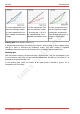
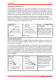
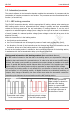
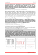
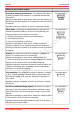
Table Of Contents
- 1. Getting started
- 2. Operation overview
- 3. Connections
- 3.1. Safety instructions
- 3.2. Safe and correct soldering
- 3.3. Avoiding irreparable damage to the decoder!
- 3.4. Pin assignment LD-G-43 | Front side
- 3.5. Pin assignment LD-G-43 | Rear side
- 3.6. Using decoders with interface connectors
- 3.7. Use of the LD-G-43 in locomotives with AC motor
- 3.8. Mounting decoders without interface
- 3.9. Connecting LEDs to the function outputs
- 3.10. Connecting inductive loads
- 3.11. Connecting the switching inputs
- 3.12. Connecting a backup capacitor or buffer circuit
- 3.13. Connection of a SUSI module
- 3.14. Completion
- 4. Programming
- 5. Configuration variables and registers
- 5.1. Overview configuration variables LD-G-43
- 5.2. Basic settings
- 5.3. Setting the address
- 5.4. Setting the motor control
- 5.5. Function mapping
- 5.6. Effects of the outputs
- 5.7. Settings for the switching inputs
- 5.8. RailCom and DCC-A settings
- 5.9. Settings for driving operation
- 5.10. Settings for analogue mode
- 5.11. Sensivity of the overload protection
- 5.12. Auxiliary functions
- 5.13. Information
- 6. Checklist for troubleshooting and error correction
- 7. Technical data
- 8. Warranty, EU conformity & WEEE

tams elektronik
LD-G-43 tams elektronik
Effects of the function outputs
Successive dimming up and down: The voltage at the output is
gradually increased when switched on or gradually reduced when
switched off.
Assignment separately for each output. Setting the time duration for
dimming up and down together for all outputs to which the function
is assigned.
Application example: Simulation of old oil or incandescent lamps.
CV programming
CV 55...62
CV 100
MARs-Light: To generate the additional warning light typical of
American locomotives (fading in and out at short intervals), the
following settings must be made for the output:
flashing and successive dimming up and down active
short flashing frequency
short time for dimming up and down
Assignment separately for each output. Setting the flashing
frequency together for two outputs. Setting the time duration for
dimming up and down together for all outputs to which the function
is assigned.
CV programming
CV 55...62
CV 100
CV 101...104
Kicking: The output first receives full voltage for a maximum of
approx. 25.5 seconds and is then switched off.
Assignment separately for each output. Setting the kick time
(= time during which the maximum voltage is applied to the output)
together for all outputs to which the function is assigned.
Application example: Some types of electrical couplings require full
voltage for decoupling. After uncoupling, however, the voltage is
switched off to protect the couplings.
CV programming
CV 55...62
CV 99
Fire simulation: The voltage at the output is reduced / increased
in short, irregular intervals, connected LEDs or lamps produce the
flickering light typical for an open fire. Assignment separately for
each output.
Application example: Simulation of the fire in the firebox of steam
locomotives.
CV programming
CV 55...62
On/Off at a defined voltage (speed): By default, the output is
switched off when the voltage is exceeded and switched on again
when it falls below. The function can be reversed by inverting the
function.
Assignment separately for each output. Setting the voltage together
for all outputs to which the function is assigned.
Application example: automatic switching on and off of the driver's
cab lighting at a certain voltage.
CV programming
CV 55...62
CV 63
18 | Operation overview