
Manual
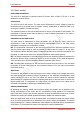
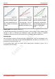
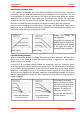
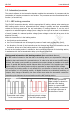
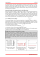
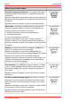
Table Of Contents
- 1. Getting started
- 2. Operation overview
- 3. Connections
- 3.1. Safety instructions
- 3.2. Safe and correct soldering
- 3.3. Avoiding irreparable damage to the decoder!
- 3.4. Pin assignment LD-G-43 | Front side
- 3.5. Pin assignment LD-G-43 | Rear side
- 3.6. Using decoders with interface connectors
- 3.7. Use of the LD-G-43 in locomotives with AC motor
- 3.8. Mounting decoders without interface
- 3.9. Connecting LEDs to the function outputs
- 3.10. Connecting inductive loads
- 3.11. Connecting the switching inputs
- 3.12. Connecting a backup capacitor or buffer circuit
- 3.13. Connection of a SUSI module
- 3.14. Completion
- 4. Programming
- 5. Configuration variables and registers
- 5.1. Overview configuration variables LD-G-43
- 5.2. Basic settings
- 5.3. Setting the address
- 5.4. Setting the motor control
- 5.5. Function mapping
- 5.6. Effects of the outputs
- 5.7. Settings for the switching inputs
- 5.8. RailCom and DCC-A settings
- 5.9. Settings for driving operation
- 5.10. Settings for analogue mode
- 5.11. Sensivity of the overload protection
- 5.12. Auxiliary functions
- 5.13. Information
- 6. Checklist for troubleshooting and error correction
- 7. Technical data
- 8. Warranty, EU conformity & WEEE

tams elektronik
tams elektronik LD-G-43
2.6. Outputs and interfaces
Function outputs
The decoder has eight function outputs (F0f, F0r, AUX1 to AUX6) with a maximum current of
300 mA each for the connection of additional accessories (e.g. lighting, smoke generator,
electrical coupling). Note: The maximum total current of the decoder (including motor) is
1,500 mA.
Function mapping according to RCN-227
Assigning the functions to the outputs follows RailCommunity standard RCN-227. It is possible
to assign one or several outputs to each function (F0 to F28, seperately for forward and
backward motion for each function). In addition, it is possible to assign another function as an
"OFF"-switch to the functions.
This mode of function mapping allows to implement special features, e.g.:
Switching on and off depending on the direction of travel.
Shunting light: When switching to shunting operation the signals for shunting operation are
switched on and those for standard operation switched off.
Switching off the locomotive´s rear lights when connecting wagons.
Effects of the function outputs
Direction-dependent switching: Assignment separately for each
output.
Function Mapping
Shunting light: Assignment separately for each output. Function Mapping
Dimming: The voltage at the output is reduced.
Assignment separately for each output.
Application example: By reducing the voltage, the lamps of older
vehicles intended for analogue operation can continue to be used in
digital operation and therefore do not have to be replaced after the
decoder has been installed.
CV programming
CV 47...54
Inverted switching: When set to "on" the assigned output is
switched off, when set to "off" it is switched on.
Assignment separately for each output.
CV programming
CV 55...62
Flashing: The voltage at the output is switched on and off
alternately.
Assignment separately for each output. Setting the flashing
frequency together for two outputs.
By assigning the flashing function to two outputs and the function
"Inverted switching" to one of the two outputs, an alternating
flashing is generated.
CV programming
CV 55...62
CV 101...104
Operation overview | 17