
Manual
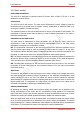
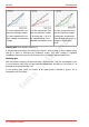
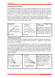
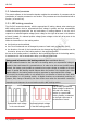
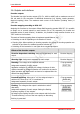
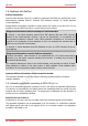
Table Of Contents
- 1. Getting started
- 2. Operation overview
- 3. Connections
- 3.1. Safety instructions
- 3.2. Safe and correct soldering
- 3.3. Avoiding irreparable damage to the decoder!
- 3.4. Pin assignment LD-G-43 | Front side
- 3.5. Pin assignment LD-G-43 | Rear side
- 3.6. Using decoders with interface connectors
- 3.7. Use of the LD-G-43 in locomotives with AC motor
- 3.8. Mounting decoders without interface
- 3.9. Connecting LEDs to the function outputs
- 3.10. Connecting inductive loads
- 3.11. Connecting the switching inputs
- 3.12. Connecting a backup capacitor or buffer circuit
- 3.13. Connection of a SUSI module
- 3.14. Completion
- 4. Programming
- 5. Configuration variables and registers
- 5.1. Overview configuration variables LD-G-43
- 5.2. Basic settings
- 5.3. Setting the address
- 5.4. Setting the motor control
- 5.5. Function mapping
- 5.6. Effects of the outputs
- 5.7. Settings for the switching inputs
- 5.8. RailCom and DCC-A settings
- 5.9. Settings for driving operation
- 5.10. Settings for analogue mode
- 5.11. Sensivity of the overload protection
- 5.12. Auxiliary functions
- 5.13. Information
- 6. Checklist for troubleshooting and error correction
- 7. Technical data
- 8. Warranty, EU conformity & WEEE

tams elektronik
LD-G-43 tams elektronik
a: Linear characteristic from
start and maximum voltage
b: Linear characteristic from
start, medium and maximum
voltage
a: Linear characteristic from
start and maximum voltage
c: Shunting gear = 50 % of
the voltage defined in the
standard characteristic curve
a: Linear characteristic from
start and maximum voltage
d: alternative characteristic
with individual assignment of
voltage to the 28 speed
levels
Starting kick (from software version 1.2)
If programmed accordingly, the starting kick causes a brief increase in motor voltage during
start-up in order to overcome the breakaway torque. The motor voltage is regulated
immediately after start-up at the set braking rate to the actually selected speed level.
Shunting gear
With the function mapping, the special function "Shunting Gear" (SG) can be assigned to one
or more functions with which it is activated and deactivated. On delivery, the function F3 is
assigned to the special function "SG".
In the shunting gear mode, the velocity of all speed levels is reduced to approx. 50 %
compared to the set velocity.
12 | Operation overview