
Manual
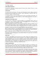
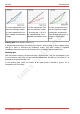
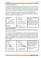
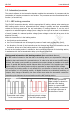
Table Of Contents
- 1. Getting started
- 2. Operation overview
- 3. Connections
- 3.1. Safety instructions
- 3.2. Safe and correct soldering
- 3.3. Avoiding irreparable damage to the decoder!
- 3.4. Pin assignment LD-G-43 | Front side
- 3.5. Pin assignment LD-G-43 | Rear side
- 3.6. Using decoders with interface connectors
- 3.7. Use of the LD-G-43 in locomotives with AC motor
- 3.8. Mounting decoders without interface
- 3.9. Connecting LEDs to the function outputs
- 3.10. Connecting inductive loads
- 3.11. Connecting the switching inputs
- 3.12. Connecting a backup capacitor or buffer circuit
- 3.13. Connection of a SUSI module
- 3.14. Completion
- 4. Programming
- 5. Configuration variables and registers
- 5.1. Overview configuration variables LD-G-43
- 5.2. Basic settings
- 5.3. Setting the address
- 5.4. Setting the motor control
- 5.5. Function mapping
- 5.6. Effects of the outputs
- 5.7. Settings for the switching inputs
- 5.8. RailCom and DCC-A settings
- 5.9. Settings for driving operation
- 5.10. Settings for analogue mode
- 5.11. Sensivity of the overload protection
- 5.12. Auxiliary functions
- 5.13. Information
- 6. Checklist for troubleshooting and error correction
- 7. Technical data
- 8. Warranty, EU conformity & WEEE

tams elektronik
tams elektronik LD-G-43
2.4. Motor control
Pulse width modulation
The LD-G-43 is designed to optimally control DC motors. With a PWM of 25 kHz, it is also
suitable for coreless motors.
Load control
The LD-G-43 has a load control. The load control influences the motor voltage to keep the
locomotive with a set speed level at constant velocity, independent of additional loads (e.g.
running up a gradient, coupled carriages).
It is possible to switch on and off the load control by varying a CV-variable of the decoder. The
parameters of the load control may be altered, in order to adapt the decoder to the motor´s
individual characteristics.
Parameters of the load control
The load control is determined by three parameters (KP, KI and KD) which have to be
coordinated in order to achieve optimal driving characteristics. Each of the load control
parameters is assigned to a configuration variable.
KP: The proportional component of the load control ensures the difference between the set
and the present value being as small as possible. It cannot have the value "0" at any time.
This component affects the basic speed. In case the set value is too small the locomotive runs
too slowly. In case the set value is too high the locomotive stutters while moving.
KI: The integral component of the load control ensures the remaining difference between the
set and the present value is reduced to 0 and so for the correction of very small divergences.
If the set value is too high the locomotive stutters massively while moving.
KD: The differential component of the load control ensures that the control is not converted
too quickly. If the set value is too low, the locomotive stutters. If it is too high, the locomotive
rocks while moving.
Gain factor
The basis for the influence of the load control on the motor voltage is the voltage returned by
the motor during the measuring period. Depending on the individual characteristics, these
values may be too high or too low. The effects are that the vehicle reaches its maximum
speed already at a speed level below the highest speed level or does not reach it at all at the
highest speed level. To compensate for these effects, the values sent by the engine can be
increased or decreased by adjusting the amplification factor.
Velocity characteristic
By adjusting the starting, middle and maximum speed, the decoder can be adapted to the
driving characteristics of the motor and the characteristic driving speeds of the locomotive
type. From these 3 points the decoder generates a speed characteristic curve which is linear
between the starting and middle speed and between middle and maximum speed.
When the speed level mode is set to 28 speed levels, it is possible to assign any motor voltage
to all of the 28 speed levels as an alternative to the linear velocity characteristic. This allows
the programming of a velocity characteristic which adjusts the individual driving characteristics
of the motor. The set values are saved in the alternative velocity characteristic.
Operation overview | 11