Manual ni k LKS-1 el ek tro Artikel-Nr.
English LKS-1 Table of contents Getting started............................................................................3 2. Safety instructions.......................................................................4 3. Safe and correct soldering...........................................................7 4. Operation overview.....................................................................8 5. Technical specifications...............................................................9 6.
LKS-1 English 1. Getting started How to use this manual ni k This manual gives step-by-step instructions for safe and correct assembly of the kit and fitting and connecting of the ready-built module, and operation. Before you start, we advise you to read the whole manual, particularly the chapter on safety instructions and the checklist for trouble shooting. You will then know where to take care and how to prevent mistakes which take a lot of effort to correct.
English LKS-1 Required materials For assembling the kit you need: k an electronic soldering iron (max. 30 Watt) or a regulated soldering iron with a fine tip and a soldering iron stand, a tip-cleaning sponge, a heat-resistant mat, a small side cutter and wire stripper, as necessary a pair of tweezers and long nose pliers, electronic tin solder (0,5 mm. diameter). ni el ek 2. Safety instructions tro In order to connect the module you need wire.
LKS-1 k ni Never perform wiring on a powered module. Assembling and mounting the kit should only be done in closed, clean, dry rooms. Beware of humidity. Only use low power for this module as described in this manual and only use certified transformers. Connect transformers and soldering irons only in approved mains sockets installed by an authorised electrician. Observe cable diameter requirements. After condensation build up, allow a minimum of 2 hours for dispersion.
English LKS-1 Dangerous environments A working area that is too small or cramped is unsuitable and can cause accidents, fires and injury. Prevent this by working in a clean, dry room with enough freedom of movement. Other dangers ni k Children can cause any of the accidents mentioned above because they are inattentive and not responsible enough. Children under the age of 14 should not be allowed to work with this kit or the ready-built module.
LKS-1 English 3. Safe and correct soldering ! Caution: ni ta m tro el ek Use a small soldering iron with max. 30 Watt or a regulated soldering iron. Only use electronic tin solder with flux. When soldering electronic circuits never use soldering-water or soldering grease. They contain acids that can corrode components and copper tracks. Insert the component connecting pins of into the PCB´s holes as far as possible without force. The components should be close to the PCB´s surface.
English Cut the wires after soldering directly above the soldering joint with a side cutter. After placing the parts, please double check for correct polarity. Check the PCB tracks for solder bridges and short circuits created by accident. This would cause faulty operation or, in the worst case, damage. You can remove excess solder by putting a clean soldering tip on the spot. The solder will become liquid again and flow from the soldering spot to the soldering tip. 4.
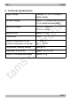
LKS-1 English 5. Technical specifications analogue a.c. or d.c. voltage or digital voltage Minimum voltage approx. 3 V (yellow and red LEDs) or 4 V (white and blue LEDs) Maximum voltage 20 V a.c. voltage or 24 V d.c. voltage Output current approx. 25 mA Protected to IP 00 ni tro 0 ... +60 °C -10 ... +80 °C el ek Ambient temperature in use Ambient temperature in storage k Supply voltage max. 85 % Dimensions of the PCB approx. 18 x 12 mm Weight of the assembled board approx.
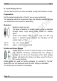
English LKS-1 6. Assembling the kit You can skip this part if you have purchased a ready-built module or device. Preparation Put the sorted components in front of you on your workbench. ni k The separate electronic components have the following special features you should take into account in assembling: Resistors 220 470 el ek tro Resistors reduce current. The value of resistors for smaller power ratings is indicated through colour rings. Every colour stands for another figure.
LKS-1 English Transistors Transistors are current amplifiers which convert low signals into stronger ones. There are several types in different package forms available. The type designation is printed on the component. ni k Transistors for a low power rating (e.g. BC types) have a package in form of a half zylinder (SOT-package). The three pins of bipolar transistors (e.g. BC types) are called basis, emitter and collector (abbreviated with the letters B, E, C in the circuit diagram).
English LKS-1 Assembly Proceed according to the order given in the list below. First solder the components on the solder side of the PCB and then cut the excess wires with the side cutter. Follow the instructions on soldering in section 3. Caution: k ! tro ni Several components have to be mounted according to their polarity. When soldering these components the wrong way round, they can be damaged when you connect the power. In the worst case the whole circuit can be damaged.
LKS-1 English ni k 7. Connecting the LKS-1 tro Fig. 2 Connections diagram Voltage supply. With d.c. voltage: minus pole VCC Voltage supply. With d.c. voltage: plus pole Anode (+) of the LEDs LED- Cathode (-) of the LEDs el ek GND Connection to (analogue) a.c. voltage ta m s When connecting the PCB to (analogue) a.c. voltage, the connections´ polarity is not relevant. The LEDs light independently of the direction of travel.
English LKS-1 el ek tro ni k travel, mount an additional bridge rectifier (e.g. item no. 83-19100-10, not included in delivery) according to the connection diagram. Fig. 3 Connecting a rectifier Connection to a decoder output Connect the connection "GND" to the appropriate output of the locomotive or function decoder. Connect the connection "VCC" to the return conductor of the output or the return conductor for all outputs.
LKS-1 English short operating duration. The LKS-1 limits the current at the output to 25 mA. Thus it is possible to connect LEDs directly (without series resistor). Connecting LEDs ni k You can connect one LED or several LEDs in series directly (without series resistor) to one LKS-1. The maximum number of LEDs you can connect to one PCB depends on the voltage supplied and the fluorescent colour of the LEDs. Maximum number of LEDs per PCB connected in series Max.
English LKS-1 8. Check list for troubleshooting Parts are getting too hot and/or start to smoke. ! Disconnect the system from the mains immediately! The LED(s) does / do not light. Possible cause: The diode D2 has been mounted with the wrong polarity. à Check the polarity. tro ni k Possible cause: one or more components are soldered incorrectly. à In case you have mounted the module from a kit, perform a visual check (à section 6.) and if necessary, remedy the faults.
LKS-1 English Hotline: If problems with your module occur, our hotline is pleased to help you (mail address on the last page). ni k Repairs: You can send in a defective module for repair (address on the last page). In case of guarantee the repair is free of charge for you. With damages not covered by guarantee, the maximum fee for the repair is the difference between the price for the ready-built module and the kit according to our valid price list.
English LKS-1 9. Guarantee bond ni k For this product we issue voluntarily a guarantee of 2 years from the date of purchase by the first customer, but in maximum 3 years after the end of series production. The first customer is the consumer first purchasing the product from us, a dealer or another natural or juristic person reselling or mounting the product on the basis of selfemployment. The guarantee exists supplementary to the legal warranty of merchantability due to the consumer by the seller.
LKS-1 English 10. EU declaration of conformity This product conforms with the EC-directives mentioned below and is therefore CE certified. ni Connect the transformer only to an approved mains socket installed by an authorised electrician. Make no changes to the original parts and accurately follow the instructions, connection diagrams and PCB layout included with this manual. Use only original spare parts for repairs. tro k 2004/108/EG on electromagnetic.
n n n tro http://www.tams-online.de n ni Information and tips: k n n el ek n n n s Warranty and service: ta m Tams Elektronik GmbH Fuhrberger Straße 4 DE-30625 Hannover fon: +49 (0)511 / 55 60 60 fax: +49 (0)511 / 55 61 61 n n n e-mail: modellbahn@tams-online.