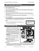
OPERATION MANUAL MST2000 SERIES Loop Powered Multivariable SMARTFLOW® Transmitter For English and Metric Unit Versions See Sec tion 15 for ap proval in for ma tion www.thermobrandt.com Let us point you in the right direction.
MST2100, NEMA 1 Thermo Brandt Instruments, Inc. P.O. Box 1190, 3333 Airpark Road Fuquay, North Carolina 27526 U.S.A. Telephone: (919) 552-9011 Facsimile: (919) 552-9716 www.Thermo Brandtinstruments.com All spec i fi ca tions sub ject to change with out no tice. HART® is a reg is tered trade mark of the HART Com mu ni ca tions Foun da tion. All other trade marks ac knowl edged.
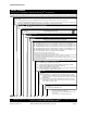
OPERATION MANUAL This manual is designed to optimize the performance of the MST2000 Series Loop Powered Multivariable SMARTFLOW® Trans mit ter. The end user should read and re view it care fully be fore install ing, us ing or main tain ing the trans mit ter. The in for ma tion con tained in this man ual cor re sponds to the re vi sion level of the soft ware shipped with your MST2000. You can down load a copy of the latest ver sion of this man ual along with other in for ma tion from our web site.
OPERATION MANUAL MODEL NUMBER SERIES: LOOP POWERED MULTIVARIABLE SMARTFLOW TM TRANSMITTER MST21 = MST2100, NEMA 1 Panel Mount En clo sure, Dif fer en tial Pres sure Con fig u ra tion & Non-isolated 4 Wire RTD In put Stan dard. u MST24 = MST2400, NEMA 4X, Fi ber glass En clo sure, Dif fer en tial Pres sure Con fig u ra tion & Non-isolated 4 Wire RTD In put Stan dard.
OPERATION MANUAL SPECIFICATIONS FUNCTIONAL SPECIFICATIONS Service: Clean, dry, non-corrosive Air or Gas. Other me dia may be pos si ble with the use of the Contin u ous Purge op tion. Con sult fac tory . Pres sure Ranges: Stan dard Pres sure Ranges: Range 1: 0 to 0.10” (0 TO 2.54mm) W.C. Range 2: 0 to 0.25” (0 to 6.35mm) W.C. Range 3: 0 to 1.0” (0 to 25.4mm) W.C. Range 4: 0 to 4.0” (0 to 101.6mm) W.C. Range 5: 0 to 16.0” (0 to 406.4mm) W.C. Range 6: 0 to 50.0” (0 to 1270.0mm) W.C.
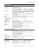
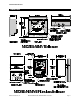
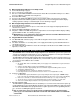
OPERATION MANUAL DIMENSIONS Brandt Instruments, Inc.
MOUNTING AND PROCESS CONNECTIONS OPERATION MANUAL 1. MOUNTING AND PROCESS CONNECTIONS The MST2000 can be mounted in any direction. There may be a minor effect on Zero that can be corrected by the setup parameters. 1.1 MST2100: NEMA 1 Enclosure A. Review the dimensional drawing on page 5. B. Pro cess con nec tions are via 1/8" NPT fe male ports lo cated on the bot tom of the hous ing. The high pressure port is la beled “HIGH”, the Low pres sure port is la beled “LOW” on the mount ing plate. 1.
OPERATION MANUAL Integral “High Pressure” Blowdown System 2.1 A. B. C. Bal ancing the Purge if the Pro cess is in Op er a tion Review the draw ing on page 5. Pro cess must be in a steady state. Dis con nect the HIGH and LOW lines from the trans mit ter. Mea sure the DP from the pro cess with a pressure calibrator or other DP mea sur ing de vice.. D. Record the DP reading. ______________________________ E. Reconnect the HIGH and LOW lines back to the transmitter. Make sure the Purge is operating. F.
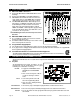
ELECTRICAL CONNECTIONS OPERATION MANUAL 4. ELECTRICAL CONNECTIONS 4.1 MST2100: NEMA 1 Enclosure A. Review the MST2100 and MST2400 dimensional drawings. B. Refer to the MST2000 Ter mi nal Block Draw ing. C. MST2000 In stru ment Elec tri cal Con nec tions are cage clamp style for 12-24 AWG. Wire should be stripped back a min i mum of 3/16" inches (5mm). D. The MST2000 Multivariable differential pressure transmitter is a HART® com pat i ble loop-powered 4-20 milliamp trans mit ter.
OPERATION MANUAL MST2000 OPERATIONAL MODES and START UP 5.2 LCD Display The MST2000 High Contrast LCD display will dis play two (2) lines si mul ta neously. The dis play is used to setup and cal i brate the MST2000 and dis play and mon i tor in put and out put sig nals and other variables. The lines of dis play are: Numeric: ! Where the val ues for DP or Flow are displayed. ! The vari ables for pa ram e ters are edited and displayed.
PROGRAMMING OPERATION MANUAL 7. PROGRAMMING The MST2000 PROGRAM mode is accessed by pressing the MODE key. When the MODE key is pressed one of the fol low ing will oc cur. þ NOTE: & The MST2000 can be Pass word pro tected to pre vent un au tho rized ac cess to pro gram ming pa ram e ters. The MST2000 is shipped from the fac tory with the Pass word dis abled. 7.1 If the Pass word Pa ram e ter is En abled (else go to Sec tion 7.2) A.
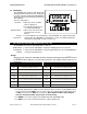
OPERATION MANUAL LEFT OF DECIMAL 1000000. PROGRAM PARAMETERS 100000. 10000. 1000. 100. 10. X1 X10 RIGHT OF DECIMAL .1 X X D1 X X X100 X X1K X X10K X D01 .01 .001 .0001 X X D001 X X D0001 X X X100K X1M 1. X X D. Af ter the num ber is changed to the de sired value, press the EDIT key again to save the new value to memory. E. The LCD will dis play saved for ap prox i mately 1 sec ond and then redisplay the new set ting. 8.
PROGRAM PARAMETERS Parameter E_AREA OPERATION MANUAL Description Fac tory De fault Effective Area of flow meter device. The effective area is required for 1.0000 for English. flow cal cu la tions and is en tered to be the same as shown on the Thermo 0.0929 for Metric. Brandt flow me ter la bel. The avail able range is: Eng lish Unit Ver sion: 0.0000 to 500.0000 square feet. Metric Unit Ver sion: 0.0000 to 100.0000 square meters.
OPERATION MANUAL Parameter EX_TPS PROGRAM PARAMETERS Description Fac tory De fault External Temperature Span. The External Temperature Span is the 200.0000 upper range setting for the external 4-20 milliamp ‘temperature’ input channel. The avail able range is: English Unit Version: 0.000 to 990.0000 degrees F. Metric Unit Ver sion: 0.000 to 990.0000 de grees C. TPSCAL Temperature Span Calibration.
PROGRAM PARAMETERS Parameter OPERATION MANUAL Description Fac tory De fault APSCAL Absolute Pressure Span Calibration. The Absolute Pressure Span Calibration value is the 20 milliamp (span) count value from the external 4-20 milliamp ‘absolute pressure’ input channel. This parameter is used to calibrate the span point of the incoming 4-20 signal from the external absolute pressure device. To calibrate the span point of the incoming 4-20 signal, press the EDIT key. The screen will display IN20MA.
OPERATION MANUAL Parameter OUTPTG PROGRAM PARAMETERS Description Fac tory De fault Output Gain. The Output Gain parameter allows the user to adjust the actual 20 milliamp (span) output value as referenced to the MST2000 displayed full scale value. The output gain parameter is displayed and stored in memory as a gain multiplier. After the EDIT key is pressed, the edit menu displays the actual multiplier value and the microprocessor sets the output to the 20.000 milliamp value.
PROGRAM PARAMETERS Parameter OPERATION MANUAL Description Fac tory De fault P_WORD Password. The password is used to prevent unauthorized access to the 0 = Password programming parameters. The password may be any value between 0 Disabled and 9999. A password value of 0 disables the password feature. BD_ENB Blow Down Enable. The Blow Down Enable parameter allows the user to enable or disable the integrated blow down sys tem. 0 = Blowdown Disabled. • A value of ‘0’ disables the Blowdown Sequence.
OPERATION MANUAL ALARM PROGRAMMING INFORMATION 9. ALARM PROGRAMMING INFORMATION 9.1 Alarm ‘ENABLE’ Word Definition The ALARM ‘ENABLE’ WORD (16 bit word) is divided into two 8 bit bytes. The lower order byte (bits 1 – 8) is used to enable and disable the alarm functions. The higher order byte (bits 9 – 16) is used t o control how the alarm is displayed and/or output to the user interface. Some bits are currently undefined and reserved for future use.
ALARM PROGRAMMING INFORMATION OPERATION MANUAL E. Latched Output: Enabling the Latched Output bit will cause any active alarm to become latched and held active even if the alarm condition clears. Any ‘latched’ alarms can be cleared during RUN mode by pressing the EDIT key (if the active alarm(s) are no longer active). After pressing the EDIT key, any latched alarms that are no longer active will be cleared and any alarms that are still active will remain latched. F.
OPERATION MANUAL ALARM PROGRAMMING INFORMATION G. Hardware Fault: Indicates hardware fault error from MST2000 internal circuitry is active. • Bi nary value = 64. H. Watchdog Timer Fault: Indicates watchdog timer fault error from internal microprocessor is active. • Bi nary value = 128. 9.
FORMULAS & CONVERSION FACTORS OPERATION MANUAL • ALARM ‘STATUS’ WORD = 206 • Using bi nary di vi sion, di vide the dec i mal word by each bi nary bit value start ing with the most significant bit value (bit 8 = 128) and then each successive lower bit. a. b. c. d. e. f. g. h. 206 B 128 = 1 with a re main der of 78 . . . . . . bit 8 (Watchdog timer fault) = 1 78 B 64 = 1 with a re main der of 14. . . . . . . . bit 7 (Hard ware fault) = 1 14 B 32 = 0 with a remainder of 14 . . . . . . . .
OPERATION MANUAL TEST JACK TEST JACK A Test Jack is stan dard on the Non I.S. Ap proved MST2000’s. It al lows the user to mon i tor the mA output of the unit with out dis con nect ing the loop. Re view di men sional draw ings on page 4. The Test Jack is removed for all I.S. and Division 2 approved MST2000’s. To monitor the mA output of the MST2000 you will need a precision milliammeter.
OPTIONAL MODULE INSTALLATION OPERATION MANUAL Align the ISO Mod ule such that the re set but ton and LED are to ward the LCD and fac ing up. The connector will be on the bot tom of the board. Snap the ISO Mod ule into the stand offs while mak ing sure the con nec tor and header are prop erly aligned. h. Re place the cover. i. Hook up the MST2000 as per the ter mi nal block wir ing di a gram on page 7. j. Ap ply Power to the MST2000. C. Programming the MST2000 to recognize the ISO Module(s) a.
OPERATION MANUAL OPTIONAL MODULE INSTALLATION b. Ex ter nal Tem per a ture Trans mit ter ISO Mod ule . Re view the Pro gram Pa ram e ters in sec tion 8. i. Con nect a 4-20 mA source to the Ex ter nal Tem per a ture Trans mit ter ISO Mod ule in put ter minals (marked EXTIN 2). See ter mi nal block draw ing on page 7. ii. Make sure pa ram e ter TMPSRC (Tem per a ture Source) is set to 1 (1 = EXTernal). iii. Set the EX_TPZ ( Tem per a ture Zero) pa ram e ter. iv.
MST2000 HART® Communications Information OPERATION MANUAL Align the HART ® mod ule such that con nec tor will be on the bot tom of the board. Snap the mod ule into the stand offs while mak ing sure the con nec tor and header are prop erly aligned. g. Re place the cover. h. Hook up the MST2000 as per the ter mi nal block wir ing di a gram on page 7. i. Ap ply Power to the MST2000. 13. MST2000 HART® Communications Information 13.
OPERATION MANUAL MST2000 HART® Communications Information Typical Point to Point Connection with analog signaling. If the ca ble is lon ger than sev eral me ters, it’s re sis tance and ca pac i tance may be come sig nif i cant in the HART® RC time-constant lim i ta tion ® x C [ 65 mi cro sec onds). When us ing a sin gle field de vice and a host with a 250 ohm load and no other sig nif i cant re sis tance, the 65 mi cro sec ond lim i ta tion would al low 0.26 uF of ca pac i tance for the sys tem.
MST2000 HART® Communications Information OPERATION MANUAL 13.6 Intrinsic Safety Con sid er ations Intrinsic safety approvals for the MST2000 are pending. Contact the factory for additional information involving hazardous applications with the use of safety barriers. 13.7 HART® Command In for ma tion The MST2000 transmitter is compliant with HART® Command Revision 5.1. The following commands are supported. Reference HART® Document HCF_LIT-20 (HART® Technical Overview) for additional information.
OPERATION MANUAL Wiring Diagrams 14. Wiring Diagrams Four Wire Con nec tion with Ab so lute Pres sure Trans mit ter Dual 2 Wire Con nec tion with Ab so lute Pres sure Trans mit ter The MST2000 with a Ab so lute Pres sure Trans mit ter can be wired to replace your ex ist ing four wire trans mit ter The MST2000 with Ab so lute Pres sure Trans mit ter can be wired to re place your ex ist ing four wire trans mit ter. Re quires two 24Vdc power sources.
Wiring Diagrams OPERATION MANUAL Power Sup ply and Ab so lute Pres sure Trans mit ter The MST2000 with Ab so lute Pres sure Trans mit ter can be sup plied with a power sup ply to power the Ab so lute Pres sure only. The MST2000 will be pow ered by a 24Vdc, 4-20mA loop. 3 Wire RTD Connection Page 30 2 Wire RTD Connection 4 Wire RTD Connection MST2000 Multivariable SMARTFLOW ® Transmitter Brandt Instruments, Inc.
OPERATION MANUAL MST2000 Haz ard ous Area In stal la tion Digital I/O Connections for Integral Blowdown System 15. MST2000 Hazardous Area Installation The MST2000 Multivariable SMARTFLOW TM Trans mit ter is Ca na dian Stan dards Asso ci a tion ap proved for the following haz ard ous area clas si fi ca tions. 15.1 In trin sically Safe In stal la tions A. Model MST2100 (NEMA 1): In trin sically Safe for CL. I, Grps. C & D B. Model MST2400 (NEMA 4X): In trin sically Safe for CL. I, Grps. C & D. CL. II, Grps.
MST2000 Hazardous Area Installation OPERATION MANUAL 15.3 Approved Options. See the chart below and re view the Model Num ber De scrip tion on Page 2.
OPERATION MANUAL Cal i bra tion of the MST2000 15.5 Notes for MST2000 I.S. Installation Draw ing SC37-4000-00 1. 2. 3. For I.S. In stal la tions, field wir ing shall be in stalled in ac cor dance with Ca na dian Elec t ri cal Code and/or Na tional Elec tri cal code ANSI/NFPA 70, Ar ti cle 504-30 Wiring ca ble shall be 24 AWG or heavier, sep a rate shielded pairs. The ground ing con nec tion be tween the safety bar rier and earth ground must be less than 1 ohm. 4.
Cal i bra tion of the MST2000 OPERATION MANUAL 16.2 DP CALIBRATION þ NOTE: For MST2000 Trans mit ters with CONTINUOUS PURGE OPTION. Do not use a hand pump, or compres sion cyl in der type of pres sure source for the DP test sig nals. You must use a vented source to per mit con tin u ous flow of purge air. Con tact the fac tory for ad di tional in for ma tion on calibrating trans mit ters with con tin u ous purge.