
Series Installation Guide
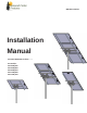


STP Mount
Series
4
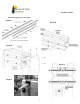
Step 4: Attach Tilt plates
Attach tilt plates, flanges facing to the outside using 3/8-16 x 1.00 bolts, flats, locks and nuts; position the tilt
plates with the top parallel to the ground (0°). Do not torque at this time, tighten only enough to hold firmly for
next assembly steps. (Detail F).
Step 5: Attach Cross Rails to Tilt Plates.
MODEL STP-LCR/120
Attach cross rails to the tilt plates, open sides facing to the inside, using 3/8 x 1.00” bolts, flats, locks and nuts.
Cross rails are to be on center across the tilt plates and parallel to each other, Torque to 20 ft-lbs. (Detail G)
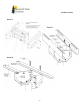
MODELS STP-SCR/045, STP-SCR/060, STP-SCR/070, STP-LCR/090
Attach cross rails to the tilt plates, open sides facing down, using a Backing Channel, 5/-16 x 2.50” bolts, flats,
locks and nuts. Cross rails are to be on center across the tilt plates and parallel to each other, Torque to 144 in-
lbs. (Detail H)
Step 6: Attach Panel Supports to Cross Rails
A. Confirm the center to center distance of the mounting holes on the PV modules and mark on the cross rails the
slots that will match that dimension.
B. Attach the panel supports with the open side facing in with the 3/8 x 1.0 bolts, flats, locks, and nuts, in the slots
that are marked, hand tighten, do not torque at this time so slight adjustments can be done on the next step.
C. Lift the PV module up onto the panel supports; align mounting holes to the panel supports so the
module is centered on the panel supports, or equally spaced for 2 or more modules. Install with 1/4 x
3/4 bolts, flat and flange nuts. Torque to 84 in-lbs.
D. Torque to 20 ft-lbs the 3/8” bolts connecting the panel supports to the cross rails.
Step 7: Adjust Tilt Angle
Remove the lower two 3/8-16 x 1.0 bolts from the tilt plates and tilt the array to desired angle, the array tilts in
10° increments from 0° to 50°. Re install 3/8-16 x 1.0 bolts and torque all six 3/8-16 x 1.0 bolts to 20 ft-lbs