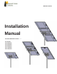
STP Mount Series Installation Manual STP-LSCR-MAN 2017 Edition v1.
STP Mount Series Table of Contents Introduction ....................................................................................................................................................... 1 Customer Support ............................................................................................................................................. 1 Tools Required......................................................................................................................................
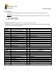
STP Mount Series Tools Required Tools that support the following size Hex heads: Torque values are “dry”, add 15% if using anti-seize lubricant on Stainless hardware (Recommended). A deep socket or short extension needed for 3/8”, in one location. 1. 3/8”= 240\20 In\Ft Lbs 2. 5/16”= 144\12 In\Ft Lbs 3. 1/4"= 84\7 In\Ft Lbs Components List The following parts are for all the STP mount models: Galvanized coated sheet steel components will show rust on cut edges and is normal and will not affect the structur
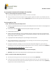
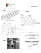
STP Mount Series Pre Assembly for Models STP-LCR/090, STP-LCR/120) Step 1: Connecting Panel Support Channels A. Lay two panel support channels end to end with a connector in the middle. B. Using a connector, bolt the panel support channels together. Tighten the 5/16-18 x 7/8” hardware (hex bolt, flat washer, and flange nut) to 144 in-lbs (dry). (Detail A) Repeat with the remaining set of channel rails and set aside. Final Assembly to Pole Step 2: Attach Pole Clamp Assembly to Pole A.
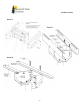
STP Mount Series Step 4: Attach Tilt plates Attach tilt plates, flanges facing to the outside using 3/8-16 x 1.00 bolts, flats, locks and nuts; position the tilt plates with the top parallel to the ground (0°). Do not torque at this time, tighten only enough to hold firmly for next assembly steps. (Detail F). Step 5: Attach Cross Rails to Tilt Plates. MODEL STP-LCR/120 Attach cross rails to the tilt plates, open sides facing to the inside, using 3/8 x 1.00” bolts, flats, locks and nuts.
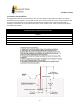
STP Mount Series Detailed Diagrams for Assembly Detail A Detail B Detail D Detail C Detail E 5
STP Mount Series Detail F Detail G Detail H 6
STP Mount Series Installer Responsibility The installer is solely responsible for: i. Complying with all applicable local or national building codes, including any that may supersede this manual; ii. Ensuring that Tamarack Solar and other products are appropriate for the particular installation and the installation environment; iii. Using only Tamarack Solar parts and installer-supplied parts as specified by Tamarack Solar. Substitution parts may void the warranty; iv.
STP Mount Series Foundation Hole Guidelines The suggestions below are recommendations only. It is the installer’s responsibility to validate foundation parameters prior to installation, as local geotechnical report may be required to assess ground conditions. We recommend consulting with a local engineer familiar with local regulations and build site requirements, including soil conditions, terrain and load criteria (wind, snow, seismic). All of these parameters may impact foundation requirements.