VMS User Manual
Preface Users installing and operating the product is required to understand this manual and relative manuals fully before installation and operation. All rights of the software and hardware described in the manual are protected by the patent law. Note This icon means “Note” explaining the procedure and additional information. This icon means “Caution” explaining important information or limitations of Caution the operation. .
CONTENTS 1. 2. 3. OVERVIEW ...................................................................................................................................... 6 1.1 INTRODUCTION ............................................................................................................................ 6 1.2 FEATURE..................................................................................................................................... 6 INSTALLATION......................................
6.2.3 6.3 6.3.1 6.4 6.4.1 6.5 6.5.1 6.6 7. EVENT LIST ............................................................................................................................... 24 EVENT INFORMATION VIEW ..................................................................................................... 24 STATUS LIST.............................................................................................................................. 24 SECURITY DEVICE STATUS INFORMATION VIEW ................
9. SECURITY DEVICE SETUP ADMINISTRATOR ........................................................................... 38 9.1 SECURITY DEVICE SETUP ADMINISTRATOR OVERVIEW ................................................................ 38 9.2 START OF THE SECURITY DEVICE SETUP .................................................................................... 38 9.3 OPEN/SAVE SETUP VALUE ......................................................................................................... 38 9.
1. Overview 1.1 Introduction This program is Central Management System that is designed to control various security devices(IP camera, DVR, NVR, Video Sever) connected from a single PC by networking. This program consists of the multi-functions including the live image monitoring, real-time event management, security device status monitoring, and then image search, playback, download, smart search and watermark etc. 1.
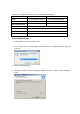
required to be equipped with more than the recommended specification. System Min. Specification CPU Recommend Specification Intel Core2Duo 2.0GHz Intel Core2Quad 2.66GHz 2GB 4GB or higher 128MB 512MB or higher Main Memory Video Card Memory Display Resolution 1024 * 768 (With 32bit color) or higher 80GB or higher HDD Windows XP SP2 or higher OS Direct X 9.0 or higher Others 2.2 Installation Guide 1. Insert software CD into the CD drive of PC. 2. Click on Setup.exe.
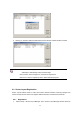
3. System Login System Login is to decide a program execution/block by confirming the user name and password. 3.1 Site Registration 1. In the program start menu, go to Netus Standard Menu and select Netus Standard icon or double-click on Netus Standard icon in the wallpaper, and then the login window pops up. 2. Select one of the names of registered users in the login window. For the first time login, select Administrator. Administrator is registered as a fundamental user. 3. Enter a password.
4.1.1 Registration 1. Select ‘Setup’->’Site Manager’ menu. Site Manager Setup window shows up. 2. In Site Manager, functions including site add, delete, modify, all select, all clear and properties are available. 3. Click on ‘Add’ and enter a security device name, description, connect address and port.
6. Clicking on ‘All Select’ makes all sites selected and ‘All Clear’ makes all sites un-ticked. Note ■ Netus Standard program automatically starts a connection to ticked addresses in Site Manager after successful login. ■ A connection doesn’t happen for un-ticked security devices. ■ There is no limit for registering sites in Netus Standard program. 4.2 Screen Layout Registration Screen Layout enables users to collect and monitor desired real-time monitoring images from various security devices.
2. Click on ‘Add’. In Screen Layout Setting window, select Channel Mode and drag cameras from the list at left and drop them onto desired locations, and then the real-monitoring image turns up. Screen Layout Name and Channel Mode must be filled for registration. 3. After finishing camera addition, users can check a newly registered screen layout in Screen Layout Manager. Users can modify and delete the screen layout as desired.
4. Users can move a list tab in Connect List to Layout and check a list of registered Screen Layout. Real-time monitoring images show up by using drag/drop onto the screen.
4.3 User Registration User Registration is to register and manage ID of the program users. It decides the program to be executed or blocked by confirming ID and password and also gives different authority to each user group for all functions in the program. Administrator as a fundamental user is registered in the administrator group. The administrator group has authority for all functions in the program. For the first time login, use initial administrator ID. Note 4.3.
5. Click on ‘Ok’ and selected functions are granted to the user group. The user group name will be shown at the user group list. Note ■ In order to register a user group, users must log in with one of ID from the administrator group. For the first time login, use the initial registered administrator. 4.3.2 1. User Registration Select ‘System’->’User Manager’ menu. User & Group Manager setup window shows up. 2. Select User tab. 3. Click on ‘Add’ at the bottom of the group list.
4. Enter a user name and password and select a group from User Group. The user name and password are the basic requirement. 5. Click on ‘Ok’ and the user name will be shown at the user list. Note ■ In order to register a user, users must login with one of ID from the administrator group. For the first time login, use initial administrator ID.
5. Menu 5.1 View View menu is a collection of the panel window to be used in the program. No.
5.2 System 5.2.1 Log Manager Log Manager is to manage an event log occurred in security devices and program function usage. 5.2.1.1 Log View 1. Select ‘System’->’Log Manager’ menu. Log Search Manager setup window shows up. 2. For the program usage log, select ‘Action’ tab. Dates saved with logs will be shown in the calendar. Select a desired date and log information will be shown. Searching by user, time and function are available. 3. For the event log in security devices, select ‘Event’ tab.
shown in the calendar. Select a desired date and log information of events and alarms will be shown. Searching by user, security device/PC time, site and event are available. 4. For the security device log, select ‘DVR Log’ tab. Dates saved with the log history will be shown in the calendar. Select a desired date and the log information of the security devices will be shown. Note ■ The time used in ‘Action’ log is based on PC time.
5.2.
1. Select ‘System’->’App Setup’ menu. App Setup window shows up. 2. In ‘Storage’ tab, users can designate saving folders for the capture image file, record file and DVR setup file. 3. In ‘OSD’ tab, users can configure the name, height, thickness and color of the font to be displayed above the real-time monitoring screen. Also it sets up Enable/Disable of the time, resolution, title and other information to be displayed above the screen. 4.
Video Covert An event that occurs when a camera is set to the covert function 7. In ‘Display’ tab, users can change the pixel size and setup the video filter. Also a size, font and color of letters; ‘Connecting’, ‘Signal Loss’ and ‘Video Disconnect’ can be decided. 8. In ‘Playback’ tab, users can setup the vertical playback mode and last image display mode. 9.
2. The name, group and group authority of the current logged-in user are displayed. 6. Viewer 6.1 Viewer Overview The viewer is a multi-channel real-time program displaying a customized screen of multi-channel real-time monitoring images. The viewer is a main function of the program and incorporates all program menus. It consists of various panels including Site Connection List, Screen Layout List, Event List, Basic Control Function and Status List Popup Image.
6.2.1 Image View by connecting security devices 1. In Site Connection List, select a desired security device icon to be monitored. 2. Drag the icon into the viewer screen, and then all channel of the security device are displayed. Note ■ To disconnect the security device, right-click on a desired icon, and then select ‘Disconnect’ in the popup menu. ■ The channel mode automatically changes according to the number of channels. ■ The max. number of channels to be displayed in the viewer are 64. 6.2.2 1.
Note ■ To disconnect the camera, drag a desire monitoring image out of the second viewer screen. Caution ■ To use more than two monitors, the video card in PC must support the dualmonitor or more. 6.3 Event List 6.3.1 Event Information View 1. In View menu, select an event list or click on button in Tool Bar. The event list window pops up. 2. Events occurred in connected security devices automatically are indicated in the event list.
Note ■ To bring thumbnail images in case of the event occurrence, tick on ‘Event Popup Image’ in ‘Instant Live’ tab at ‘App Setup’. (For more information, refer to ‘5.2.3’ App Setup.) 6.5.1 Thumbnail Image View in Popup Image Window 1. In View menu, select a popup image or click on button in Tool Bar. The popup image window shows up. 2. The thumbnail image automatically shows if an event occurs from connected security devices. (Setup needed in App Setup) 6.
PTZ Movement Control 1. Select a PTZ camera to be moved. 2. Move the PTZ camera by pressing four direction keys. PTZ Focus Control 1. Select a PTZ camera to be focus-controlled. button to adjust the focus. 2. Press PTZ Zoom Control 1. Select a PTZ camera to be zoom-controlled. 2. Press button to zoom in/out. PTZ Preset Control 1. Select a PTZ camera to be preset-controlled. 2. Select a preset number and press button. The camera moves to a preset position. 3.
6.6.2 Relay Out Control Relay Out Control is to setup the relay On/Off that is connected to the security device. The number of Relay Out varies depending on security devices. 1. Select a site to be relay out-controlled from the list. 2. Press button and request a relay out-control to the security device. 3. Status of the relay out is shown by (Off) (On) buttons. 4. The button is designed to be toggled. (On->Off, Off->On) Note ■ The time out of the relay out is 5 seconds.
Note ■ The color adjustment value returns to the default value when program terminates. 6.6.5 Screen Sequence Function Screen Sequence Function is to rotate the layout of the real-time monitoring image in the viewer screen according to a desired time interval. 1. Select a channel mode. (1, 4, 9, 16 channel mode) 2. Select a rotation time interval. (2seconds ~ 60seconds) 3. Press 6.6.6 button and it starts the rotation according to the set value.
7. Network Player 7.1 Network Player Overview Network Player allows users to search and playback recorded images and audios of the security device in multi-channel from distant PC. Users can use a preview search to find recorded images and audios. Searching and thumbnail images by a second term are available. Users can download images and audios of the desired time period into PC.
7.1.1 Playback of the Recorded Image 1. Select icon in Tool Bar. 2. Setup searching conditions(Camera/Security device, Date/Time) in the searching panel of the player at left. 3. Designate a desired time to be played in ‘Go to’ and press Note button. ■ The player can display recorded images of max. 16 cameras at the same time. (One security device) 7.2 Search Users can search recorded images and audios in the security device by two means; the time search and preview search.
Note ■ The way of the search in the player may be different from the way in the security device. 7.2.1 Time Search 1. Select icon in Tool Bar. 2. Select a security device to be played from ‘Connect List’ at the top-left. 3. Select a date and time to be searched. 4. Press button. Recorded images of the desired date/time are played on the top-right of the screen. 5. To re-setup the search condition, press Note 7.2.2 default button. ■ Users can select max. 16 cameras. Preview Search 1.
6. ‘To re-setup preview search conditions, press Note default button. ■ Users can select max. 16 cameras. 7.3 Playback 7.3.1 Playback Overview After searching images and audios by two means, searched images and audios are played automatically if the user presses a playback button. The channel mode is automatically determined according to the number of cameras. In the playback screen, the channel title, date/time and other information are displayed.
7.3.2 Time Line Time Line indicates images and audios of the designated search condition and events by each channel in graphic lines. The green line indicates that a recorded data exists. The red line means that an event recording data exists. The green space is that there is no data. Using a scroll at right, users can check the recorded event data from channel 1 to 16. 7.3.3 Playback Control It indicates images and audios of the designated search condition and events by each channel in graphic lines.
Image Enlargement (100%, 150%, 200%, 300%, 500%, 700%, 1000%, 1600%) Screen Capture Screen Print 7.4 Download In Download, users can download and save recorded images and audios from the security device to PC. 7.4.1 Download of the Recorded Data 1. Select icon in Tool Bar. 2. Select a security device to be played from ‘Connect List’ at the top-left. button and the download window pops up. 3. Press 4.
8. File Player 8.1 File Player Overview File Player is to search and play a downloaded image/audio file in the PC in multi-channel screen. Smart Search enables users to search in the thumbnail image list of the motion detection. 8.1.1 Playback of the Recorded Data 1. Select icon in Tool Bar. 2. In Tool Bar, select a data folder by pressing or button. (In ‘File’ menu, users can select ‘Folder Open’ or ‘File Open’.) 3. It starts playing recorded data files. 8.1.
data exists. The green space is that there is no data. Using a scroll at right, users can check the data of the recorded events from channel 1 to 16. 8.1.3 Playback Control It indicates images and audios of the designated search condition and events by each channel in graphic lines. Button Function Remark Fast Reverse Reverse Play Reverse one frame Pause Play one frame Play forward Fast Forward Play Speed Adjustment button for speed up, button for slow down.
8.2.1 Smart Search 1. Select button in Tool Bar. (Select ‘Smart Search‘ in ‘Tool’ menu) 2. Setup a desired area to be motion-searched. 3. Select a desired channel to be smart-searched, start date/time and end date/time. 4. In Time Interval, select ‘All Images’ or ‘Time Interval(sec). 5. Press ‘Search’ button and it starts smart-searching 6. Select searched thumbnail images and press ‘Playback’. It starts the playback from the selected time period.
9. Security Device Setup Administrator 9.1 Security Device Setup Administrator Overview Security Device Setup Administrator is to setup security devices from a remote PC directly. The administrator can save a setup value and apply it to other security devices to make the same configuration. The administrator can open and edit a setup value file. 9.2 Start of the Security Device Setup 1. Select button in Tool Bar. 2.
Caution ■ Please be aware that ‘DVR All Reset’ function resets a security device to the factory default value including the network address so that users can’t access to the security device.