FCC Compliance Statement Model Name: Deluxe, Blue, Lite 8 / 16 Channel This device complies with Part 15 of the FCC Rules. Operation is Subject to the following two conductions: (1) this device may not cause harmful interference, and (2) this device must accept any interference received, including interference that may cause undesired operations. WARNING Unauthorized reproduction of all or part of this manual is strictly prohibited.
1 2 Safety Notes on the Lithium Battery Replace lithium batteries as instructed to avoid danger. Dispose used lithium batteries properly. 【Warning and Caution are indicated as follows.】 Possible injury or product damage. Risk of minor injury or product damage. Cautions for the usage of the product. Information for the usage of the product.
Chapter 1. Introduction .................................................................. 7 1-1 HD SDI Universal series Major Features ................................................... 7 1-2 Components ........................................................................................ 8 1-3 Product Introduction ............................................................................. 9 Chapter 2. Installation and connection ..........................................
5-4-1 5-4-2 5-4-3 5-4-4 System Information .................................................................................... 34 Screen Brightness/Contrast/Color/Saturation/Sharpen/Camera Adjustment ........... 35 Display Setting .......................................................................................... 35 Screen Saver............................................................................................ 35 5-5 Control ................................................................
6-2 Camera ............................................................................................. 52 6-2-1 6-2-2 6-2-3 6-2-4 6-2-5 Camera ................................................................................................... 52 PTZ ........................................................................................................ 52 POS ....................................................................................................... 53 Event Source ...........................
[Figure 2-1. HD3-16U 16CH Basic Connection and Device Connection] ...................................... 11 [Figure 2-2. MH3-08U 8CH Basic Connection and Device Connection] ....................................... 12 [Figure 2-3. MH3-16U 16CH Basic Connection and Device Connection] ...................................... 12 [Figure 2-4. SH3-08U 8CH Basic Connection and Device Connection] ........................................ 12 [Figure 2-5. SH3-16U 16CH Basic Connection and Device Connection] .............
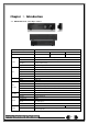
Chapter 1. Introduction 1-1 HD SDI Universal series Major Features Line Up Series HD SDI Universal DVR Deluxe Model Name System Video Blue HD3 -16u MH3-16u, MH3-08u OS Embedded Linux - Built in flash memory Access Front button, Mouse, Remocon, Network, Key controller Hexaplex Live monitoring, Recording, Playback, Backup, Network, Setup Upgrade USB2.
Line Up Alarm Series Deluxe Blue Lite Model Name HD3-16u MH3-16u, MH3-08u SH3-16u, SH3-08u Pre/Post-Alarm 5sec / 5sec~5min Alarm Action E-mail, Channel Popup, Buzzer, Relay, PTZ Preset, Spot, Remote CMS, Front LED Input / Output 4/1, 4/1, 4/1 - NC/NO/EOL HDMI ★ Full HD, XGA VGA Full HD, XGA Display External Interface HD SDI Universal DVR TV SDTV(720x480/576) Mode 16/9/4/1/SEQ - LIVE, 16/9/4/1 - P.
1-3 Product Introduction 1080P/720P/960H real-time recording 16/8 Ch audio recording 16/8 Ch spot output Various video output port (HDMI, VGA, BNC) Various video output mode (Full HD, XGA, SDTV) 6 HDD bay(HD3-16u models) 3 HDD bay(MH3-16u, MH3-08u models) 2 HDD bay(SH3-16u, SH3-08u models) Jog-shuttle 1Ch POS interface Pre-alarm recording Auto e-mailing notification max.
Chapter 2.
2-1-5SH3-16U 16CH Rear No.
[Figure 2-2. MH3-08U 8CH Basic Connection and Device Connection] [Figure 2-3. MH3-16U 16CH Basic Connection and Device Connection] [Figure 2-4.
[Figure 2-5. SH3-16U 16CH Basic Connection and Device Connection] 2-2-1 Basic Connection ※ By referring to above [Figure 2-1], make a connection accordingly.
1) SPOT Monitor Connect Spot Monitor to the rear SPOT terminal. HD SDI universal series supports 1ea SPOT terminals. 2) Audio Input/Output HD3-16U 16CH supports 16ea audio inputs. MH3-08U 8CH supports 8ea audio inputs and MH3-16U 16CH supports 16ea audio inputs. SH3-08 supports 8ea audio inputs and SH3-16 supports 16ea audio inputs. 3) Terminal Block [Figure 2-6. Terminal Block and Description] The terminal blocks in the rear of the product are for the connection of PTZ / Sensor / Relay / POS Connection.
(3) POS Connection ⑤ Connect the POS device. ⑥ Connect the POS to Terminal Block POS. The external alarm device may require the power supply depending on its type. Be cautious.
Chapter 3. Operation and Setup Tools HD-SDI Universal series can be controlled easily by using the front panel buttons, front panel, remote controller , jogshuttle and mouse. 3-1 Deluxe series Front Panel Button No.
3-2Blue series Front Panel Button No.
3-3Lite series Front Panel Button No.
3-4 HD3/MH3 series Remote Controller A) Basic Control Button POWER RECORD POWER 1 2 3 4 5 6 7 8 9 COPY ID 0 MENU RECORD 1 ~ 0 ID ESC NUMBER ID Turn the system power ON or OFF. Record all channels or stops recording all channels. Input of numeric data. Set up the remote controller ID. B) System Operation and Setup Button RELAY MENU Data, Schedule, System Set up ESC Exit the current menu or Move to the upper menu. SEARCH Search recorded images.
Example) When the remote controller ID is set to 1 Press the {ID} button, enter {0} and {1}, and press the {ID} button again. To control all DVRs with the different ID, set the remote controller ID to 999. 3-5SH3 series Remote Controller POWER Turn the system power ON or OFF. MODE FULL 1CH Mode QUAD 4CH Mode 9 SPLIT 9CH Mode 16 SPLIT 16CH Mode SEQ. Sequence Mode ON/OFF B) System Operation and Setup Button MENU ESC Data, Schedule, System Set up Exit the current menu or Move to the upper menu.
3-7 Jog/Shuttle In the playback mode, control the play direction, speed and frame. Front Speed and Direction Control Side Frame Control ※ Play Direction Control This is available in the playback mode. Turning the jog right/left plays forward/reverse frame by frame. ※ Speed and Direction Control This is available in the playback mode. Turning the jog right/left plays forward/reverse x1/x2/x4x30.
Chapter 4. DVR Operation Setup 4-1Deluxe series Storage Installation ※ Step 1 1) Using a screw driver, unscrew and take off the top case of the product. 1) Normal termination of the system and fully unplugged power code are required before conducting HDD installation. 2) After installing HDD, Do not connect to power supply with the top case opened. The top case must be covered before usage.
※ Step 3 4) Align screw holes and screw and fix HDD onto the bottom HDD bay①. 5) Align screw holes and screw and fix HDD onto the top HDD bay② 6) By reversing Step 2, combine both top② and bottom① HDD bay with the body. 1) H-model can hold HDD up to 6ea 2) HDD power and data terminal should face the inner direction. ※ Step 4 7) Connect the power cable and data cable to HDD. ※ Step 5 8) Power terminals(③). Connect the power cable into the power terminal(③).
4-2Blue series Storage Installation 1) 1) Open the top case by using screw driver. 1) Normal termination of the system and fully unplugged power code are required before conducting HDD installation. 2) Touch a grounded metal substance or ground yourself before installing HDD in order to reduce static electricity. Static electricity may cause a malfunction of the product. 3) After installing HDD, Do not connect to power supply with the top case opened. The top case must be covered before usage.
4-3Lite series Storage Installation 2) 1) Open the top case by using screw driver. 1) Normal termination of the system and fully unplugged power code are required before conducting HDD installation. 2) Touch a grounded metal substance or ground yourself before installing HDD in order to reduce static electricity. Static electricity may cause a malfunction of the product. 3) After installing HDD, Do not connect to power supply with the top case opened. The top case must be covered before usage.
4-5 Storage Setup ① Select {Menu} {Setup} {Storage} and configure HDD. For more detail about HDD and external devices, check [6-5 Storage]. 4-6 Recording Setup ① Select {Menu} {Setup} {Recording} {Recording} ② Setup [Recording Resolution]/[Recording Quality]/[Continuous Speed]/ [Event Speed]/[Audio]/[Text]. The initial recording setup is [Recording Resolution: 960H] [Recording Quality: High] [Continuous Speed: Off]. An image of the connected cameras is recorded with above setting.
4-8 Camera / TV Setup ① Select {Menu} {Setup} {Camera} {Adjust}. ② Set up for [Brightness/Contrast/Color/Hue/Camera Adjustment/TV OUT Adjustment] are available. 4-9 Display Setting and Other Setup ① Select and set up {Menu} {Miscellaneous} {Display Setting}. 4-10 External Device Setup ① Configure external devices. For more information, check [2-3 Connection of other devices], [Chapter 5. System Operation], [6-2 Definition], [6-6 Network], [6-7 System].
Chapter 5. System Operation 5-1 Real Time Monitoring Mode and Icon After booting is finished, Audio/Recording Status/Channel Title/Connection Status/Time/HDD Status are displayed as shown below. [Figure 5-8. Recording Status Window] ※ Recording Event / Recording Mode Icon ※ Motion Detection Recording Sensor Recording Recording Event Audio Recording Text Recording Video Recording Recording Mode Audio Recording Text Recording ※ Recording Event Icons are still displayed despite of the recording stop.
※ Control Bar ※ ① Full Screen ② 4 Channel Screen ③ 8 Channel Screen ④ 16 Channel Screen ⑤ ZOOM function ⑥ Auto Sequence Mode ⑦ Date / Time ⑧ HDD Status ⑨ Playback 5-2 System Login 5-2-1 User Account and Authorization System users are divided into local administrators and general users and the local administrator can use all functions. Local Admin User The local administrator can use all functions: System Power On/Off, Setup, Monitoring, and Playback .
5-2-3 Logout After logging out, the user cannot use {Menu}. ① On the real-time monitoring screen, select {Menu} {Logout}. 5-3Monitoring H-model series features powerful monitoring functions as shown below. 1 / 4 / 9 / 16 Division Mode and Auto Sequence Mode Channel Grouping 1/4/9/16 Multi spot TV out Menu Controlling in Monitoring Mode Zoom Live Event Indication Text Detection by using POS Screen Control by using PTZ.
※ The user can view an image on full screen by double-clicking a desired channel in the 4/9/16 Sub-Screen mode. Double-click any part of the screen to return to the previous mode. ※ Auto Sequence Auto Sequence is to rotate images at an interval of the certain time in 1/4/9 Basic Division. Auto Sequence is not available in the Basic 16 Division mode. ① Move to {Menu} {Miscellaneous} {Display Setup }.
[Figure 5-13. Spot] ② Move to {Menu} {Miscellaneous} {Misc. Control} {Spot} and configure on the Single mo de, Quad mode, Sequence and Channel. ③ Event Spot Event Spot is to show a channel quickly that is set with the event function in case events (Sensor, Motion and Audio) occur. The event check interval is one second. If events are detected in many channels, it shows a channel with the last event. Move to {Menu} {Setup} {Recording} {Alarm} {Spot}.
⑥ In case of the mouse, move the pointer to an area to be zoomed in the zoom control screen and double-click on it. ⑦ Then, it zooms in 3 levels; Normal, x4, x16. Those 3 levels can be controlled by the wheel of the mouse. The user also can left-click and drag the yellow box to move the focused image in higher than the x4 mode.
[Figure 5-17. PTZ Control Mini./Full.] In the PTZ mode, there are two function; Full. and Mini. Tour has [Tour1] and [Tour2]. Home Position Time is 1/5/10/User setting(1-60)minutes. Preset? Using horizontal/vertical/Zoom/Focus/Iris movement of PTZ Camera, zoom or focus or Iris a certain spot of the image by designating the coordinates and move to the designated coordinates quickly.
5-4-2 Screen Brightness/Contrast/Color/Saturation/Sharpen/Camera Adjustment Select {Adjust}, then it becomes the 1 channel mode and a window pops up as shown below. [Figure 5-19. Screen Setup Window] Moving the camera, down, right, or left excessively may cause black or gray areas to appear on the screen. The level at which such condition does not occur is the proper control range for the camera.
[Figure 5-21. Display Setting Window] 5-5 Control In the real-time monitoring, move to {Menu} {Miscellaneous} {Misc. Control}. [Figure 5-22. Audio] [Figure 5-23 . Relay] [Figure 5-24. Text] ① Move to the Audio tab and select the channel to be activated or Mute. HD-SDI Universal 16CH model support 16 channel audios and HD-SDI Universal 8CH model support 8 channel audios and HD-SDI Universal 4CH model support 4 channel audios. ② Move to the Relay tab and select. All H-model support 1 channel output.
5-6Search 5-6-1 Search Mode Move to {Menu} {Search} in the real-time monitoring mode. [Figure 5-25. Playback Menu] 5-6-2 Playback Menu (1) Calendar Search Calendar Search allows the user search and playback by [Year/Month/Day/Hour/Minute],[Multi-Channel/MultiTime/Multi-Day]and [Motion/Sensor/Audio/Pattern]. (2) Go To The Last The user can search and playback the last recorded data by Multi-Channel Mode. (3) Go To The First The user can search and playback the first recorded data by Multi-Channel Mode.
5-7-3 Time Index ① Every time when the user changes the time at {Menu} {Setup} {Time} {Date and Time} tab, a new folder(Index) is created and files saved in the folder before the time change can be fou nd at {Menu} {Calendar Search} {Time Index}. ② Selecting a file at {Menu} {Calendar Search} {Time Index} leads to a selection window pop up and the user can select a file in different folders (before time change).
5-7-8List All To check Time index in order of time line. [Figure 5-27. Time Index] 5-8POS Search 5-8-1POS Search Mode On the real-time monitoring screen, select {Menu} {Search} {POS Search} and then a searching window pops up as shown below. 5-8-2Year/Month/Day/Text/Time Selection Please select date/time, Time index, Text 1~3, and select the start time within the channel..
5-9Playback [Figure 5-29. Playback Screen] ※ There are five routes to play the recorded image. Playback in the Calendar Search Select {Playback} in {Menu} {Search} {Calendar Search} {Search}. Playback in the Go To The Last Select {Menu} {Search} {Go to The Last}. Playback in the Go To The First Select {Menu} {Search} {Go To The First}. Playback in the Last Played Time Select {Menu} {Search} {The Last Played Time}.
Button Description of the Search Buttons Name Features Channel Mode Change Switch the channel mode. Zoom Mode Switch to the Zoom mode. Press one time - Playback forward (ⅹ1) Press two times - Fast forward (ⅹ2) Press three times - Fast forward (ⅹ4) Press four times - Fast forward (ⅹ8) Forward Play / Fast Forward Press five times - Fast forward (ⅹ16) Press six times - Fast forward (ⅹ32) Forward Frame by Frame Press seven times - Fast forward (ⅹ300) Pressing one more time in x300 leads to x1 back.
Detail Search In the PAL mode, search 25 frames once. Search all frames. ① Move to the Smart Search and select the desired channel. ② After shifting to the 1 channel mode, select areas to be smart searched. [Figure 5-32. Smart Search Area Designation] ③ The 14 * 15 pixel mosaic mode appears. In the beginning, all pixels are selected. Designate an a rea by left-click and drag the pixel mosaic pointer(deep yellow). Designate another area by repeatin g the same way.
5-9-8MULTI CHANNEL Multi-Channel Search is to play recorded images of the different channel over a certain designated time. 5-9-9 Panorama Play Panorama Play is to play recorded images of the certain channel frame by frame. Panorama Play can be viewed at 16 frame / 8 frame / 4 frame / 1 frame. [Figure 5-34. Panorama Playback] 5-9-10 Event Event is to search and play events[ All/Motion/Sensor/Audio ]. 5-9-11 Backup The user can save the backup image data and capture the image into [CD/External Device].
[Figure 5-36.
[Figure 5-37 . Move to the log list of the certain time zone in Log View] Time Changed Log Data View The stored data folder is created each time the user changes the time. A blue triangular icon is displayed at a date in the calendar window that time changes are made. Otherwise, a red triangular icon is displayed at an unchanged date. To view the log details, select the desired date with a red icon. Selecting a date with the blue icon causes the changed date list window to appear.
supports USB 2.0 is connected. For supported external devices, refer to Appendix. The user can back up data in the real-time monitoring, search, log, or the playback mode. 5-12-1 Backup in The Real-Time Monitoring Mode ① In the real-time monitoring mode, select {Menu} {Backup} {Backup}. The backup menus will then appear. ② The automatic backup time is set to 5 minutes before the Copy (Backup) button is pressed, and th e end time, to the time the Copy (Backup) button is pressed.
[Figure 5-38. Backup Window] ① [Figure 5-34] shows the initial backup window menus. ② A list of the devices that can be selected is outputted with simple information of the currently selec ted devices ③ Selecting a device by pressing the Select button causes the free space and total capacity for the s elected device to be displayed. ④ Selecting a device causes the directory name based on the initial values for the time and channel to be displayed and the size of the file to be backed up to be calculated.
[Figure 5-39. Backup and Sub-menu Setup Backup] ① For the Setup Backup, a device for backup must be connected. ② Move to {Menu} {Backup} {Setup Backup} and a window shown below appears. The setup is copied by the name shown below. [Figure 5-40. Setup Upgrade] Saved as the name below. ①Model ② DVR name ③ Version ④ Date ⑤ Time ③ Move to {Menu} {Setup} {System} {6. Upgrade} ->{Setup} after insert the backup device.
5-15Capture The Capture function lets the user create a JPG file in the real-time monitoring, playback, search, or log mode and back up the image data. ① To back up the currently displayed image, select {Menu} {Backup} {Capture} in the real-tim e monitoring, Playback and Log mode. ② When only one USB2.0 backup device (excluding ODD devices) is searched, the JPG file is stored in the same device. ③ If there are no or more than two USB2.
Chapter 6. Setup 6-1Time ※ Function Description 1. Time Synchronization 1) Synchronization with the NTP server The time is synchronized once every hour with the NTP Server. A. Automatic Setup The nearest server from the user’s zone will be selected for connection. If the connection fails, the next nearest server will be chosen. B. User Setting The user sets the URL or IP for the NTP server. If connection is not established, a message will be sent to the user, and the related log, saved.
6-1-2 Date and Time (1) Date and Time Only available when Time Server is off. The system date and time format is Year/Month/Day Hour/Minute/Second. ① By using the arrow keys and the Select button, move the focus onto the desired field; Year/Month/ Day Hour/Minute/Second and press the Select button. ② Select a field you want to change by using the arrow buttons and press the Select button. (2)Time Display Format Select Time Display Format among [Day/Month/Year] / [Month/Day/Year] / [Year/Month/Day].
[Figure 6-43. Setup / Auto Reboot Menu] 6-2 Camera [Figure 6-44. Setup / Camera Menu] 6-2-1 Camera ① Connection Used to set whether to connect or disconnect each camera channel. ※ When the camera channel is set to disconnected, the video contents will not be displayed even if the camera is actually connected. ② Title Name each camera. Max. 20 letters are available. ③ Adjust Adjust Brightness/Contrast/Color/Saturation/Sharpen/Camera. 6-2-2 PTZ Setup the protocol and baud rate of the PTZ Camera.
6-2-3 POS Setup the protocol and baud rate of the POS device. 6-2-4 Event Source Select {Menu} {Setup} {Camera} {Event Source}. (1) Motion Area The user can setup the motion detection area. Area setup related to motion can be decided. [Figure 6-45. Motion Area Setup] ① Select Motion Area of each channel. ② It becomes the 1 channel division mode and rectangular boxes appear where motions occur.
[Figure 6-46. Setup / Recording] 6-3-1 Schedule Selection (Schedule1 ~ Schedule4) ① Each channel can be scheduled in 4 different schedules. This schedule can be set as the recordin g schedule and each time can be 4 different schedules. 6-3-2 Event This is to set the events On/Off of Motion / Sensor / Sound / Text Input / Text Search. Recording Type Continuous Motion Continuous recording based on the Normal Speed frame rate. When motion is detected, recording will be initiated based on the event frame rate.
(3)Frame Rate If the user configures Normal Speed and Event Speed at the same time, the continuous recording follows Normal Speed frame rate and the event recording follows Event Speed frame rate. Normal Speed Set the recording frame rate for Continuous recording.
(1) Selection Tip ① Select the day and time to be set by using the arrow keys. ② Select after moving the cursor onto Time(0-23) or Day(Sun. – Holiday) then the user can configure the whole line at once. ③ Using the mouse can be easier. (2) Holiday Registration This feature is used to enable the user to set the holidays and schedule independently. ① Move to {Schedule} {Holiday}.
① Recording The Recording storage is managed in Direct. The Recording storage stores data on the hard disk in the real time. Five commands can be executed. Depending on the S/W status, however, some commands cannot be executed. Returns the status of the selected storage device to New; if this command is executed, New the selected storage device will be moved to the {New} storage device manager. ※ Physical states supporting the execution of the commands above includes Healthy and Warning.
(3) Instruction when adding the local storage device ① ② ③ ④ Open the system body and install a new disk (connect the data cable and the power cable) Connect power to the system and boot the system. Select {Menu} {Setup} {Storage} by using the arrow keys and the Select button. A newly displayed disk will then be displayed as {New}. ⑤ Select a newly installed disk by using the arrow keys and the Select button and initialize the disk as a {Recording} or a {Backup} disk.
6-6-1Ethernet (1) TCP/IP This is to use a fixed IP in the Local Area Network environment. ① Select {Ethernet} in {Menu} {Setup} {Network}. ② Select {TCP/IP}. ③ Save after filling in IP Address, Subnet Mask, Default Gateway, Primary DNS, and Secondary DNS.
6-6-4 E-mail ① Move to {Menu} {Setup} {Network} {E-mail}. To use the e-mail function, DNS or sub DN S in {Menu} {Setup} {Network} {Ethernet} need to be configured. [Figure 6-51. Setup Network Ethernet Window] [Figure 6-52. Setup Network E-Mail Window1] This is to set automatic E-mail transmission service when an event occurs. To use the e-mail function, {E-mail} in {Menu} {Setup} {System} {9. Alarm} or {E-mail} in {Menu} {Setup} {Action} { Alarm} need to be configured.
[Figure 6-53. Setup Network E-Mail Window2] ② ③ Relay SMTP is set on ‘Gmail’ as default, but when ‘Default’ (in menu tab) is selected, this will changed to dvr@cctvuser.com. Receiver Email can be set up to 5 users (emails). ④ Email Interval settings are as follows [5 sec / 1 min / 3 min / 5 min /10 min]. 6-6-5 Bandwidth Move to {Menu} {Setup} {Network} {Bandwidth}.
2. ID For Remote Controller 3. ID For Key Controller 4. User Registration 5. Admin. Password 6. Upgrade 7. Factory Setup 8. POS 9. Alarm 10. Alarm Duration 11. Menu Time Out 12. Language 13. Video Loss Event Delay Time Used to name the remote controller for running the system. Unique system controller number setting. Used to register, add, or delete users. Used to set the password of the Local System Administrator. Upgrades the system firmware/system setup Initialize Setup.
6-7-4 User Registration ※ Add, edit, or delete the users who will operate the system and give authorities to users as shown below. System Access Authorization View the real-time images upon network access. View the recorded images. Copy and download files. PTZ camera control Recording, schedule, system, storage, Time, PTZ, Setup network, Screen setup Network Upgrade Remote network upgrade Covert channel monitoring View the covert channel in the network.
② Read the information and select {Yes} to start the upgrade gradually. Select {No} to return to the {System} mode. ③ After the upgrade is completed, the system reboots. ④ Move to {Menu} {Miscellaneous} {DVR Information} {3. Software Version} to check the v ersion. (3) Setup Upgrade ① Select {Setup} and the upgrade file list stored in the selected device and simple version informatio n of the selected file are then displayed. ② Select a file and then the upgrade starts immediately.
menu. 1/2/3 MIN User Setting If there is no input from the front button, remote controller, or mouse, the system will shift to the real-time monitoring mode. The user can enter the time directly. ※ The time can be set to 1 ~ 60 minutes. ③ Selecting the User Setting causes the input window to appear. ④ Enter the time by using the numeric buttons or the arrow keys and the Select button. 6-7-12 Language This feature is used to select the language for the On Screen Display (OSD) menu of the system.
APPENDIX A/P/P/E/N/D/I/X Recommended PTZ Camera Protocol NO Vendor Model Protocol 1 A.D.
67