H.264 Network DVR H.
H.264 Network DVR Table of Contents CHAPTER.1 Product Introduction....................................................................................................... - 6 1.1 Overview........................................................................................................................................................................................................ - 6 1.2 Features............................................................................................................
H.264 Network DVR 5.1 PTZ Control ................................................................................................................................................................................................- 34 5.1.1 Connection...............................................................................................................................................................................................- 34 5.1.2 Preparation ...................................................
H.264 Network DVR 8.1.2 Connection Settings.................................................................................................................................................................................- 62 8.1.3 ActiveX Download Installation ..................................................................................................................................................................- 65 8.2 Remote Connection ..............................................................
H.264 Network DVR Caution and Preventive Tips Power Supply These DVRs operate on 12V DC; the 4-CH @ 4.16A and the 8-CH at 6A. If you don't plan to use the DVR for an extended period please turn off and un-plug the power supply. Safety These DVRs are intended for use indoors only. To prevent risk of electrical shock don't use these DVRs outdoors or in areas of high moisture. A DVR is a delicate device and you should leave service of the unit to a qualified technician.
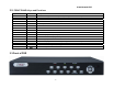
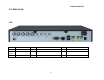
H.264 Network DVR CHAPTER.1 Product Introduction 1.1 Overview This series of DVRs represents a high level of engineering and design providing high quality digital monitoring for CCTV applications. Linux operating system and embedded processors, high-performance coding and decoding chipsets, advanced IT technology; such as audio codec, high capacity storage hard disk, TCP / IP network and more, make these systems more stable, the image clearer and more powerful functionality.
H.264 Network DVR 1.2 Features Real-time Monitoring Compression Format Composite video out/VGA output 1/4/8 multi-screen display; displays real-time video and resources occupied per hour. Channel marks display status; recording, motion detection, video loss, video block, alarm triggered. Supports system search via local access. Video compression format: H.264. HDD USB interface for external USB stick or drive. Back-up to another PC or drive via network.
H.264 Network DVR 4/8ch alarm input (alarm can be triggered by normally open or normally closed switch), Video loss alarm, Motion detection alarm. Trigger device can be a smoke detector, temperature detector, infrared detector, etc. Relay switch alarm output to link an alarm system or live lighting control. Alarm Communication Interfaces Interface for alarm input and PTZ control. Standard Ethernet interface for remote access via network.
H.264 Network DVR 2.2.
H.264 Network DVR 2.4.
H.
H.264 Network DVR 2.5 Remote Control Operation Use the remote to control the DVR.
H.264 Network DVR No. Name 1 POWER 2 REC 3 SEARCH Description No. Power on/Power off Name 8 1/4/8 screen modes switch 9 Pop-up the soft keyboard Pop-up the relative menu in preview Pop-up the relative menu in playback Recording control Press to SEARCH.
H.264 Network DVR CHAPTER.3 Basic Operation 3.1.
H.
H.
H.264 Network DVR If a hard drive has not been installed you will receive a prompt as below: (Figure 3-1) Figure 3-1 3.1.3 Shut down Correct Shut Down: A. Press and hold the POWER button approximately 3 seconds then confirm shut down of the system; this will stop all the functions of the DVR. (Figure 3-2) Figure 3-2 B. Enter into the menu and select “Shutdown System” in exit system menu.
H.264 Network DVR Figure 3-3 Incorrect Shut Down: A. Avoid turning off the master POWER switch on the rear panel. While the DVR is running, you can shut it down immediately by the power switch on the rear panel; avoid this (especially while recording). B. Avoid unplugging the power cable. While the DVR is running, you can shut it down immediately by unplugging the power cable; avoid this (especially while recording).
H.264 Network DVR 3.3 Preview Upon normal startup the DVR will enter into the preview screen. The preview screen will display the current time and date, the name and status of each channel. The screen icons and their description are below. 1 This icon is displayed on any channel that is recording 3 This icon is displayed on any channel if motion is detected 2 This icon is displayed on any channel with video loss 3.4 Record Each channel can record in different modes depending on specific needs.
H.264 Network DVR 2) Recording operation interface instructions AUTOMATIC - The channel will automatically begin to record based on the preset settings. MANUAL – The highest priority level; without regard to the recording state of any channel, clicking the manual button will cause all channels to begin recording. STOP - Stop all recording ALL- Select all channels 3.4.2 Playback There are two playback modes: fast playback and advanced playback.
H.264 Network DVR Figure 3-6 SEARCH DATE - The record date of the files that you want to search. START TIME/END TIME - The record time period of the file that you want to search, start time should be less than end time. PLAY TYPE - Playback according to the file or according to time. SEARCH TYPE - Select the file type that you want to search, options are: ALL, TIME, ALARM, MOTION. SEARCH CHANNEL – Select 4 or 8 channels.
H.264 Network DVR Button Description Button Description Button Description Play/Pause Stop Slow play From fast play, slowly play to normal Fast play Mute Volume File Single-screen mode Four-screen mode Hide the progress bar Exit Descriptions: 1) The speed, channel, time, and process are displayed in the playback control panel. 2) The playback control is effective for all channels when the videos are played according to precise time.
H.264 Network DVR Figure 3-8 DETECT – Connect a backup device to the system, click the detect button to display the type, partition, capacity and other information of the device. After attaching another backup device, click detect again. REMOVE - Click remove button to safely detach a backup device from the system. STOP - Suspend the backup task. (A DVD burner model cannot stop midway.) ADD - Search for the files needed for backup. CLR SEL - Remove single or multiple backup files selected in the list box.
H.264 Network DVR Figure 3-9 Backup retrieval During the backup procedure, the figure at the right bottom will show the current completed progress. Users can view the backup video files, and the files always have a kind of format: Channel number+ year/month/day. NOTE: During the backup process the figures at the bottom of the dialog box will display real-time progress. CHAPTER.4 Menu Operation 4.1 Menu Preview Main Menu Submenu Remark Main menu Video search and playback.
H.
H.
H.264 Network DVR 4.2 Menu Operation "Menu”(Figure 4-1) Figure 4-1 The main menu has nine functions including playback, system info, system setup, recording control, hard disk, alarm control, advance, file, files backup and exit. Explication: Click on the check-box to select an operation.
H.264 Network DVR 4.2.1 System Information “Menu” → “SYSTEM INFO”. (Figure 4-2) System information includes: hard disk, log, version and net user.
H.264 Network DVR (1) Disk information “Menu” → “SYSTEM INFO” → “DISK INFORMATION” (Figure 4-3) Display the types, socket positions, total capacity and usable capacity of the hard disk connected to device.
H.264 Network DVR (2) Log information “Menu” → “SYSTEM INFO” → “LOG INFORMATION”. (Figure 4-4) Displays log information of the system. The users can search the file log information easily. "LOG TYPE" Select; all, system, set, data management, warning, video operation, user management. "START TIME" Set the start point of a log inquiry. "END TIME" Set the end point of a log inquiry.
H.264 Network DVR (3)Version information “Menu” → “SYSTEM INFO” → “VERSION INFORMATION”. (Figure 4-5) Displays the version of system software, hardware and MCU, including release date.
H.264 Network DVR (4) Online user “Menu” → “SYSTEM INFO” → “NET USER”. (Figure 4-6) View information about online users, including account name and IP address.
H.264 Network DVR 4.2.2 Disk Management “Menu” → “HARD DISK” (Figure 4-7) Displays the current hard disk attributes: type, total capacity, usable capacity. Click an activity button to complete operations such as format hard drive. Figure 4-7 Note: Stop recording before formatting the hard disk.
H.264 Network DVR CHAPTER.5 System Control 5.1 PTZ Control 5.1.1 Connection 1) Connect the speed dome camera’s control cable to DVD’s RS-485 port. Pay close attention to + , - polarity. 2) Connect the camera's video cable to the DVR video input. 3) Connect power to camera. 5.1.2 Preparation 1) Set the control address of the speed dome camera, choose the corresponding protocol. 2) Switch the current picture to display channel. 5.1.
H.264 Network DVR Note: Change the iris, focus and zoom mode through "MODE" key, it can also control the LENS+ and LENS-. 5-2 Operation "Scan Limit" Pan the camera left and set the left limit, pan the camera right and set the right limit. "Auto Scan" Select to start the camera scan automatically between the right and left limit side. "Pattern Set" Select to record all paths of the PTZ camera and save it when stop. "Auto Iris" Select to allow the system to automatically adjust the camera iris.
H.264 Network DVR Figure 5-3 Adjust the Brightness, Chroma, Contrast, and Saturation of picture, use the mouse wheel or ←→ key to make adjustment with precision. 5.3 Sound Monitoring The user can monitor the sound corresponding to the displayed image. Right click the mouse on the channel to be monitored, click "open monitor" from the pop-up shortcut menu. If the option has already been selected the option will be "Close monitor". 5.4 Alarm Control 5.4.
H.264 Network DVR Figure 5-4 5.4.
H.264 Network DVR Press the "Clear" key to stop the current alarm record and output. But not disarm, may trigger the alarm again. Icons explication: All alarm input channels are at arm status. One or several alarm input channels are at arm status. One or several alarm input triggers the alarm, click this icon and pop-up "Clear alarm" window to display the alarm information.
H.264 Network DVR CHAPTER.6 System Setup "Main Menu" - "System Setup" (Figure6-1) System Setup includes ”System”, “Encoding”, “Recording”, “PTZ”, “Network”, “Alarm”, “Detection ”, “Display”. Note: A user can only enter into the system setup with appropriate authority.
H.264 Network DVR 6.1 System Setup "Main Menu" - "System Setup" System Setup(Figure 6-2) Figure 6-2 "System Time" Set the current DVR system date and time, Click “Set Time” to save the setup. "Date Format" Set the date and format options, including year/month/day, month/date/year, day/month/year etc. "Separator" Three options: “-” “/” “.” For example; choose “.” To display the date as 2009.02.25. "Time Format" 24 or 12 hour. "Language" Language options.
H.264 Network DVR 6.2 Encoding Setup "Main Menu" - "System Setup" - "Encoding Setup". (Figure 6-3) Figure 6-3 "Channel" Choose the channel to setup, ALL applies the same setup to all channels. "Encode Type" Two options; “Audio&Video” stream or “Video” stream only. "Encode Size" CIF, HD1, D1. "Stream Control" Two options; "variable rate" and "fixed rate". "Encode Quality" Six options for picture quality; best, very good, good, general, poor, low.
H.264 Network DVR 6.3 Recording Setup "Main Menu" - "System" - "Recording Setup" (Figure 6-4) The DVR default recording mode is 24 hours continuously. The DVR recording mode can be set to meet the users' application. Figure 6-4 "Disk Full" There are two options when the DVR hard drive is full; “Over write” the oldest files and continue to record and “Stop Video recording”. "Duration" Set the maximum time an event will record to a file between 5 and 120 minutes. "Channel/Schedule" Drop-down menus.
H.264 Network DVR 6.4 PTZ Setup "Main Menu" - "System" - "PTZ Setup" (Figure 6-5) Figure 6-5 "Channel" Choose the channel to connect a speed dome camera, "ALL" means all channels. "DEV Address" Set the address(es) of speed dome camera(s). The numerical ranges 0-255. Note: The address must be consistent with the speed dome cameras, or the DVR can't control the cameras. "Protocol" Choose the corresponding control protocol: Pelco_P, Pelco_D, the default is Pelco_D.
H.264 Network DVR 6.5 Network Setup "Main Menu" - "System" - "Network Setup" (Figure 6-6) Figure 6-6 Figure 6-7 "Ethernet IP" Set the IP address. Figure 6-6 "Netmask" Set the IP network mask address. "MAC Address" Set the physical address of the network card. The digital input is hexadecimal. (Figure 6-7) "Gateway" Setup the gateway IP address. Figure 6-6 "DNS" Setup DNS server IP address. "Server Port" The default is 7777, set according to the user need. Requires a system restart.
H.264 Network DVR Note: After PPPoE dial up successful, user may visit the DVR remotely according to PPPoE IP displayed IP address, In local area network, can visit the DVR through the network card. Figure 6-7A 6.5.1Email Function Setup (Figure 6-7A) "Mail Server" Enter the e-mail service provider server address. Example: smtp.gmail.com "Sender Address" Enter the sender address. Example yourname@gmail.com "Sender User Name" Enter the sender user name; should correspond to the mail address.
H.264 Network DVR 6.6 Alarm Setup "Main Menu" - "System" - "Alarm Setup" (Figure 6-8). Figure 6-8 "Alarm Input" Choose the corresponding alarm channel number, “ALL” means all channels. "Device Type" Alarm input “Normal Open” or “Normal Close” options. "Alarm Reset After" Setup the corresponding delay time (5~255 seconds) for the event to be recorded prior to reset. "SEQ Display" Set to trigger the DVR to sequence through the connected cameras on the display when an alarm triggers the system.
H.264 Network DVR 6.7 Video Detection Setup "Main Menu" → "System Setup" → "Detection." (Figure 6-9) Explanation: 1) Voltage changes within the video channel are detected as motion. The screen will show that motion has been detected by displaying the motion alarm symbol. 2) The system features drag and drop simplicity to setting the dynamic range of the motion detection region. Press and hold the left mouse button to set up the detection regions.
H.264 Network DVR "CHANNEL" Select the video channel(s) to set motion detection, choose "all" to apply motion detection to all channels. "ALARM TYPE" Select Motion Detection setting. "ALARM DELAY" Set the corresponding delay time (5 ~ 255 seconds), when the motion ends the system will record to the set point of the delay. "RECORDING" Select the desired video channel for motion alarm recording. This mode allows the system to record by video motion detection during a scheduled time period.
H.264 Network DVR 6.7.2 Video Loss Set the system to respond to video loss or unconnected video channels. (Figure 6-11) Figure 6-11 "CHANNEL" Select the channels to set video loss feedback. "ALARM TYPE" Select the detection settings: Video loss. "ALARM DELAY" Set corresponding delay time (5 ~ 255 seconds) the system will alert after an alarm activity. "ALARM DEV OUT" Set the alarm output that corresponds to a video channel.
H.264 Network DVR 6.7.3 Video Blind Alerts that a camera has been blocked or flooded with light in an attempt to "blind" the camera. The shelter alarm alerts the user that this condition may be in effect. (Figure 6-12) Figure 6-12 "CHANNEL" Select the channels to set shelter alarm feedback. "ALARM TYPE" Select the detection settings: shelter detection. "ALARM DELAY" Set corresponding delay time (5 ~ 255 seconds) the system will alert after an alarm activity.
H.264 Network DVR 6.8 Local Display “Main menu” → “System setup” → “Display” (Figure 6-13) Figure 6-13 "CHANNEL NAME" Select the channel name button, enter the channel name (e.g. LOADING DOCK). "WINDOW COLOR" Select the display color for the menu window. "TRANSPARENCY" Set for transparency level for the menu window. "SEQ Display" Set eh system to switch sequentially through the system inputs. "TIME" Set the dwell time for the camera to display, from 5s to 120s.
H.264 Network DVR CHAPTER.7 System Management "Main Menu" → "Advance" to show sub-menu, including: user accounts, exception handling, system maintenance, output regulation, restoring the default.
H.264 Network DVR 7.1 User Account "Main Menu" → "Advance" → "User Account." (Figure 7-2) Figure 7-2 User names can be up to eight characters; any combination of letters, numbers and symbols. The system will accommodate up to unique 12 user names. Admin users can modify user names, passwords and permissions. Lower level users can modify their password and can view allowed video channels. To change a password, select the user name to be changed, enter the current password.
H.
H.264 Network DVR Add new users and set user permissions control or increase a user's access to the user's menu interface. Enter your user name, user password and confirm password. Configure the list of users and their access level. "Allow duplicate log" eneable multiple users to log in under the same user name. (Figure 7-5) Figure 7-5 There are three default users: admin, user, default, the three users can not be deleted. Admin user has the highest authority level and may carry out all operations.
H.264 Network DVR 7.2 Exception "Main Menu" → "Advance" → "Exception" (Figure 7-6) Figure 7-6 "Exception" Select abnormal operation; hard disk is full, hard disk error or network disconnection. "Buzzer Alarm" Select if there will be a buzzer alert to an abnormal operation. "Alarm Output" Set an alarm output in conjunction with abnormal operation. Note: The user can view detailed log record of abnormal operation.
H.264 Network DVR 7.3 System Maintenance "Main Menu" → "Advance" → "Software Upgrade" (Figure 7-7) Figure 7-7 "System Upgrade" Select the source device holding the upgrade software from the dropdown menu and click upgrade. "Auto Reboot" Select auto reboot and set the occurrence and time as necessary. Click confirm to complete the action.
H.264 Network DVR 7.4 Output Adjustment "Main Menu" → "Advance" → VGA Adjust." (Figure 7-8). Manage the VGA output adjustment region, color brightness and resolution. 7-8 Note:"restore"→"Local display", select this to reset the output to factory default.
H.264 Network DVR 7.5 Restore "Main Menu" → "Advance" → "Restore" (Figure 7-9) You can set multiple options back to factory default. Select the sub-system to reset and click confirm to complete the operation. Note: Menu Color, Language, Date & Time format, system, IP address, User account won't revert to factory default.
H.264 Network DVR CHAPTER.8 Remote Network Control and Management 8.1 Remote Settings 8.1.1 Network Security Settings Set internet security level before install ActiveX. (1)Open Browser (i.e. Internet Explorer), select ”Tools” - “Internet options” (2) In the dialog box that appears, select the "Security" tab.
H.264 Network DVR (3) Click on "Custom Level", enter the security settings. (Figure 8-2) Figure 8-2 ActiveX controls and plug-ins installed The DVR requires you to install ActiveX controls to see the video stream and Internet Explorer asks if you want to install the ActiveX control.
H.264 Network DVR 8.1.2 Connection Settings The DVR can be accessed by another PC on the network or on the internet. Following is the information needed to set up the DVR for network access. 1. Right-Click "My Network Places" on your PC desktop. From the pop-up menu, click on "Properties", open "Network Connections." 2. Double-click to open "Local Area Connection.
H.264 Network DVR 3. Click "Properties" to open local area connection properties.
H.264 Network DVR 4. Double-click "Internet Protocol (TCP / IP)" to open the setting screen. (Figure 8-5) Figure 8-5 5. The setting screen displays the PC's IP address, subnet mask, default gateway. (Figure 8-5. Your network parameter setting may be different than shown. 6. Copy the corresponding subnet mask, and default gateway to the DVR (see section 6.5 Network Settings). The IP address must not be the same as the PC, this will result in a network conflict.
H.264 Network DVR 8.1.3 ActiveX Download Installation After completing the DVR network settings, open the internet browser and enter the IP address of the DVR and select "install the ActiveX control", the PC will automatically download and install ActiveX control (Figure 8-6). Figure 8-6 If the DVR ActiveX have a new version is available, IE browser will automatically update if prompted. Please update ActiveX to ensure that the client ActiveX are not in use, or else fail to update 8.
H.264 Network DVR Figure 8-7 "Login Mode" There are two options to log into the DVR system. 1) IP Address: enter the DVR's IP address into the web browser. 2) Domain Name: If you use a DDNS service you can use the domain name to access your DVR directly or through your router. "Port" DVR port number and network port number must be set the same.
H.264 Network DVR If login fails, an error message will pop-up. Check the IP address, port number, user name, password. (Figure 8-8) Figure 8-8 After a successful login the PC will display the DVR screen below.
H.264 Network DVR 8.2.2 Multiple Servers Login Click Login on the right side of the DVR screen to login to other servers simultaneously. 8.2.3 Channel Associated Menus Right-click in the preview window, the pop-up menu below will appear. (Figure 8-10) Figure 8-10 "Full Screen" Enlarge the interface to fill the screen. "Full Display" Enlarge the displayed video to fill the screen. "Start audio" Enable audio monitoring. "Stop Preview" Stop the current channel preview.
H.264 Network DVR 8.3 Control Click "Control" on right side of the DVR screen to open the "Select Server" dialog box. (Figure 8-11) Figure 8-11 Select the required Server to display on the PC screen.
H.264 Network DVR 8.3.1 Common Control "Reboot server" Select to reboot a DVR server. "Shut down server" Select to close a DVR server. "Remote Upgrade" Select to begin a system software upgrade. Upgrade will start if files are available.
H.264 Network DVR 8.3.2 Video Remote adjustment of DVR parameters; brightness, color, contrast, saturation.
H.264 Network DVR 8.3.3 Log Remotely access the DVR system log. (Figure 8-15) Figure 8-15 "Start time / End time" Select the time period to review. "Log type" Select the type of log to review; system log, configuration log, data log, alarm log, recording log and user management.
H.264 Network DVR 8.3.4 Download Remotely access the DVR to download video files to archive on the PC, network drive of burn to CD/DVD. (Figure 8-16) Figure 8-16 "Channel" Select the channel to search. "Record type" Select the recording type; all, recording, alarm recording, motion recording "Start time / End time" Select the time period to review.
H.264 Network DVR 8.4 Setting Click "Setup" on the right side of the DVR screen to open the Setting menu.
H.264 Network DVR Figure 8-17 8.4.1 Local Setting "Common Setting" "GUI Language" Select the GUI language; Chinese or English "Video Window Color" Set Video Window Color: RGB Color parameters setup "Record Setting" "Directory" Select the location to record on the local PC. "Reserve Disk Space" The system will not use this space on the local PC.
H.264 Network DVR 8.5 Toolbar Introduction 8.5.1 Real-time Preview Control Upon logging into the server the user can remotely preview the DVR video in real time. After successful login the server, users can remote preview DVR images in real-time. Select an unused window and click the "Start" button, the video channel will pop-up and shows that it in preview mode. To save real-time video to a specified directory on the PC or a network storage drive click the RECORD button.
H.264 Network DVR Figure 8-19 8.6 Other Operations 8.6.1 PTZ and Preset Control Figure 8-20 The direction buttons control a PTZ camera. The respective arrows control direction; up, down, right, left. Click the center button to set camera preset points and adjust the camera. 8.6.2 Lens Control Figure 8-21 "+ Focus -" Controls the focus ring of the camera. "+ Auxiliary -" May be assigned to a needed function on the camera. "+ Zoom -" Adjust the focal length of the lens.
H.264 Network DVR 8.6.3 Window View Modes Figure 8-22 8-settings: Single camera sequencing, four camera view, six camera view with one primary image, eight camera view with one primary image, or eight small camera view.
H.264 Network DVR CHAPTER.10 Mobile phone client software operation Mobile phone model supported currently: S60 Nokia N73, N71, N75, N76, N77, N78, N79, N80, N81, N82, N85, N86, N91, N92, N93, N93i, N95, N96 Mobile phone client software installation: 1. First, download software from the CD to your mobile phone and then install the software. Click DVR icon shown below picture 9-1 to enter software.
H.264 Network DVR 2. Open software, enter server address and port number. Click Login icon to open surveillance software interface. 3. Upon opening the software interface, follow the mobile phone function button presentation below. Note: Before use this software, please firstly select corresponding GPRS server from mobile phone server list.
H.264 Network DVR CHAPTER.10 FAQ Connected to the power, the machine didn’t start running 1. Check whether the power switch is turned on. 2. Check whether the adapter is plugged in and connected to the DVR. Hanging at the boot screen 1. The hard disk may have physical damage. 2. The system guide is un-normal. Starting very slow 1. A hard disc error can cause the mother board to check the hard disk repeatedly. Host restart repeatedly 1.
H.264 Network DVR Operating system update failure 1. USB device incompatibility, try a new USB drive. 2. Bad USB connection. The image on the monitor is black and white 1. Check the video input, DVR, monitor or TV is exactly the same video format, if it isn’t, please change the setting to automatic. No image on the monitor 1. Check the status of the monitor; power on, brightness. 2. Check the monitor video cable. Video ripple or tearing 1. Check for shorts in the video cables. 2.
H.264 Network DVR Mosaic appears in the server’s videos playback 1. The low parameters would cause the whole quality of videos, and then Mosaic may appear in the playback. 2. Bad disk sectors may lead to the appearance of Mosaic during the playback. ActiveX of client can’t be updated automatically 1. Whether the IP address accessing server is correct. 2. Whether the settings of browser are correct (refer to 8.1.2). 3. Please turn off the window if it’s open. 4.
H.264 Network DVR Appendix A: Technical Specifications 4CH 8CH Video Compression Video Input 4ch (Simple Edition) H.264 4ch (1.0Vp-p/75Ω,BNC) 8ch (1.0Vp-p/75Ω,BNC) Video Output 4ch (1.0Vp-p/75Ω,BNC) 3ch (1.
H.264 Network DVR Appendix B: Alarm Input Interface Instruction 4/8CH alarm input, no input limitation any N/O or N/C contact. NC terminal of alarm detector connect to DVR alarm input (ALARM) If the user wants to attach a detector (such as smoke detector) external power must be used. The external power should share the same ground with the DVR if the device is supply by external power.
H.264 Network DVR Appendix C: Alarm Output Interface Instruction 4CH switch alarm output, the user can use N/O or N/C contacts. The external alarm device must use external power.