DR4000 / DR8000 / DR1600 H.
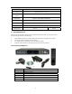
We highly encourage our customers to bench test their system prior to installation. Bench testing will confirm all components are operating properly and will help familiarize you with the system prior to installation. Lay your system components out on a large surface such as a test bench or kitchen table and inventory items. Connect cameras to the DVR video inputs, a monitor or TV to the DVR video output, and then connect power to the cameras.
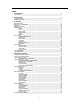
INDEX 1 INTRODUCTION_____________________________________________________________ 4 Specifications ________________________________________________________________________ 4 2 INSTALLATION _____________________________________________________________ 6 Product Overview _____________________________________________________________________ 6 Hard Drive Installation _________________________________________________________________ 7 3 OPERATION _____________________________________________________________
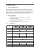
1 INTRODUCTION 1.1 PRODUCT INTRODUCTION This compact DVR has all the functionality you desire. H.264 video compression ensures maximum recording time, while preserving the quality of the recorded video. Ethernet connection provides access from any computer on your home network and even remotely over the Internet or your Smartphone. An intuitive onscreen GUI eases system setup and exporting recorded video. Video motion detection saves hard drive space and alerts you to movement in an observed area.
Network interface RJ45,100M/1000M PTZ Supported (Pelco-D, Pelco-P) Communication interface RS485×1, + / - / gnd Data storage Support 1 SATA HDD; 300GB-2TB Mouse USB Mouse Remote control IR remote included I/O 0~2V; Low voltage alarm / 5~30V; High voltage alarm Voltage input 12V/3A 12V/5A 1.3 ENVIRONMENTAL Safety precautions should be employed while installing and using this DVR.
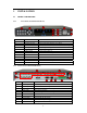
2 INSTALLATION 2.1 PRODUCT OVERVIEW 2.1.1 Front Panel (16-Channel DVR Shown) 1 NO. 1 2 3 4 5 6 7 8 9 10 11 12 2.1.2 3 2 Name Channel Select Playback direction Status indicators Rec/Stop Play Display toggle Menu PTZ ESC Cursor navigation USB Power 10 4 5 6 7 8 9 11 12 Function Select a video channel for full-screen view Stop, Fast Forward, Rewind, Next, Back Power, (Net) Link, Alarm, HDD Full, Record, IR Target Start or stop recording Begin video playback Toggle single, quad, etc.
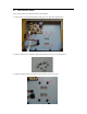
2.2 HDD INSTALLATION Follow the steps below to install the hard drive into the DVR. 1)Remove the cover from the DVR and locate the four screw holes and ventilation slots. 2)Remove the four screws and foam isolation pads from the accessory box; see photo below. 3)Remove the paper backing and place the isolation pads over the screw holes.
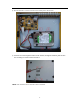
4)Place the hard drive over the screw holes and isolation pads as shown below. 5)Insert the screws through the bottom of the chassis, through the isolation pads and into the mounting screw holes of the hard drive. NOTE: After installation the new hard drive must be formatted.
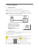
3 DEVICE OPERATION 3.1 MOUSE OPERATION The mouse is the primary input device for navigating system menus. NOTE: Unless otherwise noted, all functions described in this manual use mouse input. To use a mouse with the system connect the mouse to the USB MOUSE port on rear of the DVR. NOTE: The USB ports are exclusive to the device intended. The top USB port is for data backup to a USB flash drive, the bottom port is for connecting a USB mouse. Figure 1.
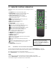
3.2 REMOTE CONTROL OPERATION The remote control is the secondary device for navigating the system’s interface. 1. STANDBY: Press to turn on/off standby mode. 2. LOGIN/LOCK: If "Security" has been enabled in the setup menu, press to open the user login screen. 3. Number/Channel buttons: While in menus buttons enter values; during live viewing, press to view channels in full-screen. 4. : Press to switch between quad and split-screen. 5. MENU: Opens the main menu. 6. PTZ: Opens the PTZ control interface. 7.
3.3 MENU TREE Use the mouse to control the DVR and navigate the menus. The tree diagram below is a quick reference to help keep track of menu levels and functions. The menu functions are explained on the following pages.
3.4 SYSTEM OPERATION 3.4.1 USER LOGIN 3.4.1.1 STARTING THE SYSTEM To power the system ON/OFF connect the power cable to the DC 12V port on the rear panel. At startup, the system performs a basic system check and runs an initial loading sequence. After a few moments, the system loads a live display view. 1) If there is no HDD in the device, the device can't read the HDD, or the HDD isn't formatted it will display an "H" in the video on the screen. 2) You must format the HDD in the DVR before first use.
3.4.2 GUI OPERATION The main menu; "DISPLAY", "RECORD", "NETWORK", "SEARCH", "DEVICES", and "SYSTEM". Note: The menu will display the sub-menu functions when you mouse over the menu icon. 3.4.2.1 DISPLAY Click "DISPLAY" on the main menu to enter the display settings interface. CH01 ~ CH04: Click to select the channel to change settings. CHN NAME: Click to enter channel description names into the system. POSITION: Click to switch name location; there are 5 options.
Click and drag the cursor to adjust settings. Click "APPLY" to save the parameters 3.4.2.2 RECORD SETUP Click "RECORD" on the main menu to enter into the record settings interface. CH01~CH04: Click to select the channel to change settings. RECORD: Open: Channel recoding enabled, Close: Channel recording disabled. BITRATE: Click to select the bitrate for best data compression.
CHANNEL: Click to select all channels or just one channel for schedule recording. WEEKLY: Setup each channel as desired, there are three modes; ALARM, NORMAL, NO REC, the selected mode will display a "check mark". You can copy a daily setting to other days. Different colors indicate different record mode: Red for alarm record, green for normal record, blank for no record. Click APPLY then Enter to save new settings. 3.4.2.3 NETWORK SETUP Click the "NETWORK" to enter network settings interface.
DHCP Select "DHCP" for the DVR to automatically negotiate an IP address from the router. PORT: This is the out-bound port for video transmission. WEB PORT: This is the in-bound contact port for HTTP. DDNS Select "Open" if you are using DDNS or "Close" if you are not using DDNS service with your DVR. SERVICE: The DVR supports 3 DDNS services; 3322, dyndns, and perfecteyes. HOST NAME: Input the host name you created when you opened your DDNS account.
3.4.2.4 SEARCH Click "Search" on the main menu to enter into the search settings interface. DATE: To narrow your search criteria you can enter date and time directly into the fields by overtyping the current date and time. You can use the mouse and virtual keyboard or use the numeric keys on the remote control. Click "Search", click "Apply" to view the recorded information. MONTH: Displays the recording status in the displayed month; Green = Normal, Red = Alarm, and No background color = No Recording.
DETAIL FILES In the Record search menu click on a date to select, click on "Detail Files" then "Apply"; this will display a list of video files for the day. You can then select up to four channels to play back at the same time. Instruction: 1. "DETAIL FILES"; "Chn" is the channel the video is recoded to, "Size" is the size of the file (in MB), "Type" is the type of recording file; normal or alarm. You can "Select" channels and export to a USB (thumb) drive by clicking "Backup". 2.
BACKUP You can backup files directly from the DVR onto a USB flash drive. The DVR supports USB 2.0 and USB OTG devices. Insert the USB flash drive into the USB port before you begin to backup files. Select the files by clicking in the "Select" box. You can un-select files by clicking in a "Select" box that has been checked. Click "Backup" to begin exporting files to the USB flash drive. If the backup files are larger than available space on the flash drive the DVR will display "Space no enough".
3.4.2.5 DEVICE SETUP Click "DEVICE" on the main menu to enter into the device settings interface. Advanced Features include HDD, ALARM, PTZ, MOBILE and MOTION DETECT. HARD DRIVE MANAGEMENT Click "HDD" to enter the hard drive settings interface. HDD STATUS: "OK" indicates that the HDD is operating properly. A malfunctioning or unformatted HDD will indicate "Failure". In the case of a HDD failure or unformatted HDD an "H" will be displayed on the live view. You can reformat the HDD from this menu.
ALARM SETUP Click "ALARM" to enter the alarm settings interface. CH01~CH04: Click to select the channels for alarm setup. I/O ALARM: Select "ON" or "OFF" for alarm contact closures. HDD LOSS: Select "Open" to trigger an alarm if there is no HDD, an "H" will display on the bottom left of channel 1 in live view. HDD SPACE: Select "Open" to trigger a notification in live view if there is less than 500 MB storage on the HDD. This is only applicable if HDD Overwrite is enables.
Email: Enable = On, Disable = Off SSL is a security link transport protocol that allows you to encrypt your communication information, including your email. Using SSL helps to prevent hackers from monitoring your email or communication information, even your password. Please confirm with your email service provider that your email server supports SSL. SSL: Enable = On, Disable = Off SMTP (Simple Mail Transfer Protocol) is an internet standard for e-mail transmission via IP networks.
PTZ Control From the live view screen, right click for the drop down menu. Click on PTZ to bring up the PTZ control menus below.
MOBILE Click "MOBILE" to enter the mobile phone settings interface. You will need a smart phone with web access and a data plan to use this option. USER NAME: Enter the user name used to logo into the DVR; for example "admin". PASSWORD: Enter the password used to log into the DVR; 519070 is the default. SERVER PORT: Enter the port number for mobile view. This port must be forwarded in your router. Please note that the DVR server port is not the same value as the mobile server port.
Using the remote control: Use the direction key to move the cursor to the desired grid segment; green indicates the cursor is on a specific grid segment, press enter to activate the segment. When set-up is complete select exit to return to the previous menu screen. Using the mouse: Move the mouse to the desired grid segment; green indicates the cursor is on a specific grid segment, left click to activate the segment. When set-up is complete select exit to return to the previous menu screen.
DATE/TIME SETUP Click "TimeDate" to enter the time and date settings interface. Stop DVR recording prior to setting the date and time. DATE: Overtype the date setting in the date field using the virtual keyboard or the number keys on the remote control. DATE FORMAT: Click to choose your preferred date format; YY/MM/DD or MM/DD/YY. TIME: Overtype the time setting in the time field using the virtual keyboard or the number keys on the remote control.
VIDEO/AUDIO SETUP Click A/V Setup to enter the A/V settings interface. NORM: Click to select your country's video standard; NTSC (US) or PAL (Europe). POLL TIME: Set the time interval between channel / group changes. SEQUENCE: Set the sequence cameras / groups will change. VGA RESOLUTION: Click to select the video resolution for the "VGA" output; 1024*768, 1280*1024, 1920*1080, 1440*900. VOLUME: Click "Volume" to enter settings for the volume level.
SYSTEM INFORMATION Click "INFORMATION" to enter the system information setting interface; displays system hardware features and firmware version, including: Device ID, Software Version and MAC Address. SYSTEM MAINTAINANCE Click on "MAINTAIN" to enter the system maintenance setting interface. AUTO MAINTAIN: Click to set the DVR for auto maintenance. Close turns off auto maintenance, Open turns on auto maintenance and allows you to schedule regular system reboots.
REBOOT: Click to restart the DVR. This is common after making important system changes. POWER OFF: Click to shut down the DVR. 4 NETWORK OPERATION 4.1 USE CLIENT SOFTWARE TO OPERATE THE DVR FROM YOUR PC With the DVR connected to your network the Client Software allows you to operate the DVR from your PC. 4.1.1 Install NVClient software The Client Software can be found on the CD included in the accessory box. 4.1.1.1 Load the CD into your CD/DVD drive and open the "CMS" file folder.
4.1.2 Log into NVClient The first time you launch NVClient you will set up a User Name and a Password. This username and password is for NVClient software only and not used to log into your DVR. You will use this name and password each time you launch NVClient in the future. Username: Enter a username that you will use each time you launch NVClient. Password: Enter a password that you will use each time you launch NVClient. Re Input: Confirm the password that you will use each time you launch NVClient.
4.1.2.2 Common Setup Tab Under server manage click on "Add" to enter the Add Server settings interface. Server Type: Click to choose the DVR server type; select 37DVR. Address: Enter the IP address of the DVR from the network setup menu. Local Name: Assign a name to easily recognize a DVR if you have more than one. CMD Port: Enter the port number used on your router to stream video from the DVR. Stream Type: Select Main Stream. Enable Auto Logon: Click to allow NVClient to log into the DVR.
NOTE: The user name and password used to log into the DVR may or may not be the same user name and password used to log into NVClient. 4.1.3 Log out of NVClient Exit: Click the "X" in the top right corner to exit NVClient. Username: Enter your NVClient user name, I. E.: admin Password: Enter your NVClient password. 4.1.4 Log into NVClient Once you have set up the parameters in NVClient you can begin to use the software to access your DVR.
4.2.1 Sign up for a dynamic domain name at DYN.com Click: "Get Started With DNS" Click: "DynDNS Free" at the bottom of the screen. Click: "Get It Now" Hostname: enter a hostname of your choosing I.E.: talosdvr along with an extension I.E.: dyndns.tv IP Address: Enter the IP address at the location the DVR will be running. The IP address of your current location is shown below the IP Address field. We recommended you set up your DYN account using a PC connected to the network the DVR will be connected.
4.2.2 Set up the DVR for access using a dynamic domain name service 4.2.2.1 Network settings TYPE: Select "Static" to set your preferred DVR IP address on your network. PORT: This is the out-bound port for video transmission; enter 7777. WEB PORT: This is the in-bound contact port for HTTP. The normal value is 80, if your ISP blocks 80 you will need to select a different port number like 8081. IP ADDRESS: Set an IP address and press "Enter".
Click "Apply" then "Exit" then reboot your DVR for changes to take effect. 4.2.3 Setup the Router for Port Forwarding We are using a popular Linksys router for our example. Refer to your router user manual or visit portforwarding.com for instructions to forward ports in your router. 4.2.3.1 Log into your router Use a web browser like Internet Explorer to access the router setup interface. Address: Enter the IP address of your router then press enter, I.E.: 192.168.1.
4.2.3.2 Administration tab Click: Administration tab Remote Management: Click disable 4.2.3.3 Applications & Gaming tab Application: Enter a name to identify the application, I.E.: Tal DVR Start: Enter the staring port for a range of ports to forward. 7777 for DVR video streaming, 80 for http: access from the internet, and 8888 for the mobile port. END: Enter the ending port for a range of ports to forward. It is OK to have the same port number in both start and end.
4.2.3.4 Setup tab It ahs been our experience that some systems might require the DDNS setup in the router, if this is the case with your system, use these instructions. Click: Setup tab Click: DDNS tab Select: dynDNS.org Username: Enter your DDNS user name Password: Enter your DDNS password Host Name: Enter your DDNS host name, I.E.: talosdvr.dyndns.tv Click: Update 4.2.4 NVClient Load NVClient software onto a remote PC connected to the internet. Follow the instruction beginning at 4.1.
NOTE: The user name and password used to log into the DVR may or may not be the same user name and password used to log into NVClient. Setup Ex: Allows you to set automatic logo server functions. Enable Sync Time On Server Open: Check On Start App, Auto Open Server: Check On Check Camera: Select "Open Image at Free Position" On Open Server: "Select Auto Open Camera" Enable Back Connect: Check Listen Port: Enter the port number used on your router to stream video from the DVR; 7777. 4.2.5.
4.3 USE INTERNET EXPLORER TO OPERATE THE DVR FROM ANY PC CONNECTED TO THE INTERNET The DVR has a web server built-in that allows you to operate the DVR using Internet Explorer, without the need for client software. This is very handy if you are using an office or a friend's computer and do not want to load software. You can use IE at home or remotely. Use the DVRs IP address at home; I.E.: 192.168.1.222 or use your DDNS host name if you are away from your home.
4.3.2.2 Security Tools: On the IE toolbar, click on the "Tools" tab. Internet Options: In the drop down menu click on "Internet Options". Security: In the Internet Options menu click on "Security". Custom Level: In the Security Settings menu click on "ActiveX controls and plug-ins". Enable: Click "Enable or Prompt" for each option under ActiveX controls and plug-ins. Exit IE: Click "OK", then "Apply", then "OK". Close Internet Explorer to save the new set-up. 4.3.2.
4.3.3 Log into the DVR Enter your domain name (over internet, WAN) or the DVR IP address (over your network, LAN). Username: Enter the user name you have set in your DVR, I.E. admin. Password: Enter the password you use to log into your DVR. The DVR will load the "Live" view from the cameras using the built-in web server.
4.3.4 WEB SERVER INTERFACE There are four setting options in "Live view"; LIVE, REPLAY, REMOTE SETTING< LOCAL SETTING, and LOGOUT. 4.3.4.1 LIVE Click "LIVE" to view a live feed from the cameras through the DVR web server. In "LIVE" view you have control of a PTZ camera, recording to the local PC, and camera layout view. PTZ CONTROL PTZ Control allows you to control a camera equipped with PTZ functions. Direction Control allows you to tilt the camera up/down or pan the camera left/right.
4.3.4.2 REPALY (IE Browser) You can play saved video from the DVR using the web server. Click the "REPLAY" tab to enter the playback interface. Select the date of the saved video on the calendar, if the list is not generated, click on "REFRESH". From the "FILE LIST" you can narrow down your selection by channel and/or recording type. Click on the selected file then press "PLAY" to play the file from the DVR or "DOWNLOAD" to copy the file to the local PC.
4.3.4.3 REMOTE SETTING Click "REMOTE SETTING" to enter the Remote Setting interface. Within the remote setting interface you can set parameters for Video Encoding, Record setting, Alarm setting, PTZ setting, Network setting, Advanced setting, and System information seven menus. ENCODE SETTING Video Parameters setting allows you to change the way the DVR encodes video to maximize storage space and video streaming.
Color Adjust setting allows you to change the video and color levels making camera images look more natural and easier to see. Note: you can copy settings to any or all channels using the "COPY SETTINGS TO…" button. RECORD SETTING Click "Record Setting" to enter the record setting interface.
Rec Enable allows you to decide if a video channel is recorded. Unit of Pack allows you to set the max size of the video file making it easier to download and save. Rec Mode allows you to set the DVR to record at; Power Up, Manual, or by Timer. Audio Enable allows you to turn audio recording on or off. Audio recording requires microphones. Time OSD allows you to r the time display ON or OFF per channel while recording.
PTZ SETTING Click "PTZ Setting" to enter the Pan Tilt Zoom camera setting interface. Channe allows you to assign the settings to a specific camera and DVR channel. Protocol allows you to select the control language the DVR will use to communicate with the camera. Address allows you to match the DVR channel and camera; DVR and camera address must match. Buad Rate allows you to set the rate at which information is transmitted from the DVR to the camera.
MOBILE SETTING Click "Mobile" to enter the mobile settings interface. Port is the port on your router used for streaming to a Smartphone Network Type allows you to choose the type of network used by your Smartphone or tablet.
ADVANCED SETTING Click "Advanced Setting" to enter the advanced settings interface. System Setting Language allows you to change the language for the DVR graphical user interface. TV Mode allows you to set the video system for the country you will operate the DVR in. Time Zone allows you to set the time zone the DVR will operate in with reference to GMT. Daylight Savings Time DST allows you to tune daylight savings time ON or OFF. DST Mode allows you to choose between default and custom DST.
Maintenance System Operate Operation allows you to set the DVR to original factory parameters or to reboot, click execute. Upgrade File allows you to locate an upgrade file saved on your PC and load it to the DVR, click upgrade. Auto Maintenance Enable allows you to toggle ON or OFF. Mode allows you to set the frequency of auto maintenance; reboots the DVR. Time allows you to set the time of day for auto maintenance. Setup allows you to save the settings. Refresh sets enable to OFF and clears all fields.
Hard Disk Info List Displays the hard drives installed into the DVR and their status, total size, and remaining storage. USER SETTING Click "User Setting" to enter the user setting interface. Access Account Account allows you to set the account number for a user; 1 ~ 5. Enable allows you to turn an account ON or OFF; accounts 2 ~ 5. User Name allows you to assign a user name to an account. Password allows you to assign a password to accompany a user name.
LOCAL SETTING Click "Local Setting" to enter the local setting interface. Record Save Path allows you to set a path to a folder for saving video recorded from the DVR server to the local PC. Frame Save Path allows you to set a path to a folder for saving an image captured from the DVR server to the local PC. File Save Path allows you to set a path to a folder for saving video downloaded from the DVR server to the local PC. LOGOUT Click "Logout" to return to the login screen.