Digital Video Recorder User Manual Digital Video Recorder
Digital Video Recorder User Manual Statement: This manual may contain information that does not match the product. If you have any unsolved problems in the process of using this product according to this manual, please contact our technical support department. The content of this manual may be updated at irregular intervals without prior notice. This manual is for reference only. DVR’s functions and operations with different models may be different.
Digital Video Recorder User Manual Table of Contents Chapter 1 Product Introduction ......................................................................................1 1.1 Overview ............................................................................................... 1 1.2 Main Features ........................................................................................ 1 Chapter 2 Installation Guide ..........................................................................................
Digital Video Recorder User Manual 4.5.2 Motion ....................................................................................... 20 4.5.3 Sensor ...................................................................................... 20 4.5.4 Reboot the System ...................................................................... 21 4.6 Alarm Configuration ............................................................................... 22 4.6.1 Sensor ...................................................
Digital Video Recorder User Manual Chapter 6 Remote Surveillance ....................................................................................56 6.1 IE Remote Surveillance.......................................................................... 56 6.1.1 On LAN ..................................................................................... 56 6.1.2 On WAN .................................................................................... 57 6.2 Remote Live Preview ............................
Digital Video Recorder User Manual 7.6.4 Switch Channel .......................................................................... 88 7.6.5 PTZ Control ............................................................................... 89 7.6.6 Local Video ................................................................................ 90 7.6.7 Saved Photos ............................................................................. 91 7.6.8 Switch Language ....................................................
Digital Video Recorder User Manual Chapter 1 Product Introduction 1.1 Overview This model of DVR (Digital Video Recorder) is designed for high performance CCTV solutions. It adopts state of the art video processing chips and embedded Linux system. Meanwhile, it utilizes most advanced technologies, such as standard H.264 with low bit rate, Dual stream, HDMI interface, SATA interface, VGA output, mouse supported, IE browser supported with full remote control, mobile view(by phones), etc.
Digital Video Recorder User Manual BACKUP Supports USB 2.
Digital Video Recorder User Manual SECURITY Customize user privileges: log search, system setup, shut down, two way audio, file management, disk management, remote login, live view, manual record, playback, backup, PTZ control and remote live view Supports 1 administrator and 63 users Supports event log recording and checking NETWORK Supports TCP/IP, DHCP, PPPoE, DDNS protocol Supports browser remote viewing Supports setup client connection Supports dual streams adjustable to f
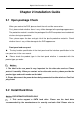
Digital Video Recorder User Manual Chapter 2 Installation Guide 2.1 Open-package Check When you receive the DVR, please check the unit and the accessories: First, please check whether there is any visible damage to the package appearance. The protective materials used for the package of the DVR can protect most accidental clashes during transportation. Then, please open the box and get rid of the plastic protective materials. Check whether there is any visible damage to the DVR appearance.
Digital Video Recorder User Manual “Appendix C Compatible Devices 2”. 2. Please calculate HDD capacity according to the recording setting. Please refer to “Appendix B Calculate Recording Capacity”. Step1: Disassemble the screw and open the top cover. Step2: Connect the power and data cables. Place the HDD onto the bottom case as Fig 2-1. Step3: Mount the HDD. Fig 0-1 Connect HDD Notice: 1. For installation please connect the power and data cables first, and then the screws to secure the HDD. 2.
Digital Video Recorder User Manual The descriptions of front panel interface are shown as follows: Fig 0-2 Front Panel Item Name 1 IR 2 HDD 3 ACT 4 LINK 5 REC 6 MENU 7 ESC 8 Direction and Enter Description Receive the signal of remote controller. Hard disk status indicator. When HDD is writing or reading, the light is white. Network data indicator. When exchanging data in the network, the light is white. Network connection indicator.
Digital Video Recorder User Manual Fig 0-3 Rear Panel Item Name 1 V-IN 2 A-IN 3 A-OUT 4 V-OUT 5 HDMI port 6 LAN port Network connector. 7 VGA port VGA output: connect to monitor. ALM IN 8 ALM OUT GND 9 USB port 10 RS-485 11 DC 12V Description Video signal input. Audio input: connect to pickup and other audio collecting equipment. Audio output: connect to sound box and other audio output equipment. CVBS video signal output: connect to monitor with BNC interface.
Digital Video Recorder User Manual 2.5 Remote Control The remote controller of this product series uses two AAA size batteries: Step 1: Open the battery cover of the remote controller Step 2: Place batteries. Please take care the poles (+ and -) Step 3: Replace the battery cover Notice: Frequently defect checking as following: 1. Check batteries poles 2. Check the remaining charge in the batteries 3.
Digital Video Recorder User Manual Item Name 4 Digital Button Code input/number input/channel switch. 5 EXIT Button Return to the previous interface. 6 BACKUP Button To enter the backup mode. 7 SEARCH Button To enter the video playback interface. 8 SEQ Button 9 E-ZOOM Button 10 MENU Button 11 12 13 Multi Screen Button Single Screen Button Direction and Enter Button Function To enter the auto dwell mode. To electronic amplify the single channel. To enter the sub menu.
Digital Video Recorder User Manual Step 3: Cancel controller to control DVR: without any action on keys about half a minute later, the DVR will not be controlled by remote controller. 2.6 Control with Mouse 2.6.1 Connect Mouse It supports USB mouse through the USB ports. Note: If mouse is not detected or doesn't work, try another mouse. 2.6.2 Use Mouse In live: Double-click left button on one camera to be full screen display. Double-click again to return to the previous screen display.
Digital Video Recorder User Manual In PTZ control: Click left button to choose the buttons to control the PTZ. Click right button to return to live mode. Note: Mouse is the default tool in all the operation below unless otherwise noted. Chapter 3 Basic Functions 3.1 Power On/Off 3.1.1 Power On Before you power on the unit, please verify all the connections. Step 1: Connect with the source power; switch on the power button near the power port in the rear panel.
Digital Video Recorder User Manual Step 1: press Power button of remote controller to pop up Shut Down window. Step 2: click OK, the unit will power off after a while. Step 3: disconnect the power. By mouse: Step 1: enter into Main Menu and select Shut Down button to pop up Shut Down window. Step 2: Click OK, the unit will power off after a while. Step 3: Disconnect the power. 3.2 Login User can login and logout the DVR system.
Digital Video Recorder User Manual 3.3 Live Preview Fig 3-2 live preview interface Symbol Meaning Green Manual record Yellow Motion detection record Red Alarm record Blue Schedule record 3.4 Live Playback Click of control menu to playback the recordings, refer to Fig3-3. User can click the control buttons on the screen to change operation.
Digital Video Recorder User Manual Fig 3-3 live playback 5
Digital Video Recorder User Manual Chapter 4 Main Menu Setup Guide 4.1 Control Menu Right click to display the control menu, refer to Fig 4-1: Fig 4-1 control menu Single: Click this button to pop up the single channel selection box. Multi: Click this button to pop up the multi-channel selection box. The range of options synchronizes with configured device. Images can be dragged to any place to display in the live interface. Dwell: Display the preview pictures in the dwell mode.
Digital Video Recorder User Manual Record: Click this button to record current video. Playback: Click this button to playback the recorded files; click the relevant buttons on the screen to control playback. Main Menu: Click button to pop up the window shown in Fig 4-2; then click Setup button to pop up the window shown in Fig 4-3. Fig 4-2 main menu Fig 4-3 setup menu Press MENU button on the front panel or operate with remote controller also can display the main menu.
Digital Video Recorder User Manual 4.2 Basic Configuration Basic configuration includes three submenus: system date & time and DST. 4.2.1 System Enter into Main MenuSetupBasicSystem; refer to Fig 4-4: User can setup the device name, device ID, video format, max online users, video output, language, etc. Fig 4-4 basic configuration-system Device Name/ID: The name/ID of device. It may display on the client end or CMS that help user to recognize the device remotely. ID range: [0~65535].
Digital Video Recorder User Manual Note: When switching between BNC, VGA and HDMI this will change the menu output mode, please connect to the corresponding device for control. Language: Select the menu language; built-in multi-languages. Note: Change the language or video output, the device needs to login again. Screensaver[S]: Set the screensaver interval time. If there is no any operation within the period specified, the device will automatically logout and return to login interface.
Digital Video Recorder User Manual 4.2.3 DST Enter into Main MenuSetupBasicDST; refer to Fig 4-6: Enable “Daylight Saving Time”, and set time offset, mode, start & end time. Click “Default” button to restore the default setting; click “Apply” button to save the setting; click “Exit” button to exit current interface. Fig 4-6 basic configuration-DST 4.3 Live Configuration Live configuration includes three submenus: live, main monitor and mask. 4.3.
Digital Video Recorder User Manual All: Select “all” and then do relevant setup, user can set all channels with same parameters. Live Rec Status: In upper left corner of the screen will appear a status icon when manual or triggered recording is active. Click “Default” button to restore the default setting; click “Apply” button to save the setting; click “Exit” button to exit current interface. Fig 4-7 live configuration-live Fig 4-8 live-color adjustment 4.3.
Digital Video Recorder User Manual Fig 4-9 live configuration-main monitor Click “Default” button to restore the default setting; click “Apply” button to save the setting; click “Exit” button to exit current menu. 4.3.
Digital Video Recorder User Manual area of video image. An image can be entirely or partially masked, it supports 4 areas maximum. Click right mouse to return to the previous interface. Refer to Fig 4-10(a) and Fig 4-10(b): Delete mask area: Select a certain mask area, double click left mouse to delete that area, click right mouse to return to previous menu. Click “Default” button to restore the default setting; click “Apply” button to save the setting; click “Exit” button to exit current menu.
Digital Video Recorder User Manual Fig 4-11 record configuration-enable 4.4.2 Record Bitrate Enter into Main MenuSetuprecordrecord bitrate; refer to Fig 4-12: Fig 4-12 record configuration-record bitrate Set the resolution, frame rate, encode, quality and max bitrate. Select “all” and then do relevant setup, user can set all channels with same parameters.
Digital Video Recorder User Manual setting; click “Exit” button to exit current menu. Note: If frame rate surpasses the maximum resources of device, the value will be adjusted automatically.
Digital Video Recorder User Manual Post-alarm Record Time: Set the delay time to stop the record after the alarm is finished. Expire [Days]: The hold time of recorded files. If the recorded files are overdue, they will be deleted automatically. Select “all” and then do relevant setup, user can set all channels with same parameters. Click “Default” button to restore the default setting; click “Apply” button to save the setting; click “Exit” button to exit current interface. 4.4.
Digital Video Recorder User Manual Fig 4-14(a) Before drag Fig 4-14(b) After drag 4.4.5 Recycle Record Enter into Main MenuSetupRecordRecycle record. When the storage space is full, “Recycle Record” will cover the earliest storage files and keep recording, otherwise it will stop recording and generate an alarm automatically. Select “Default” button to restore the default setting; click “Apply” button to save the setting; click “Exit” button to exit current menu.
Digital Video Recorder User Manual 4.5 Schedule Configuration Enter into Main MenuSetupSchedule. Schedule configuration includes four submenus: schedule, motion, sensor and reboot the system; refer to Fig 4-15: 4.5.1 Schedule Fig 4-15 schedule configuration-schedule The column means the seven days of a week from Monday to Sunday; the row means 24 hours of a day.
Digital Video Recorder User Manual button to copy the specified day schedule to other dates. Click “OK” button to save the setting, click “Exit” button to exit current interface. Fig 4-16 schedule configuration-week schedule Step 4: User can copy and apply channel settings to the other channel or all channels. Click “Copy” button to copy the specified channel schedule to other channel.
Digital Video Recorder User Manual 4.5.2 Motion The interface of motion detection configure is shown in Fig 4-17: Fig 4-17 schedule configuration-motion The setup steps of motion are similar to the schedule; user can refer to 4.5.1 schedule for details. Note: The default schedule of motion detection is full-selected, that is, the color of schedule setting interface is blue. 4.5.
Digital Video Recorder User Manual Fig 4-18 schedule configuration-sensor The setup steps of sensor are similar to the schedule; user can refer to 4.5.1 schedule for details. Note: The default schedule of sensor alarm is full-selected, that is, the color of schedule setting interface is blue. 4.5.4 Reboot the System The interface of timing reboot configure is shown in Fig 4-19. User can open the timing reboot function of device, set reboot date and time, it supports 3 time configurations.
Digital Video Recorder User Manual 4.6 Alarm Configuration Enter into Main MenuSetupAlarm. Alarm configuration includes five submenus: sensor, motion, video loss, other alarm and alarm out. 4.6.1 Sensor Sensor includes three submenus: basic, alarm handling and schedule. 1. Basic Refer to Fig 4-20. User can enable sensor alarm of alarm input; select the alarm type according to alarm trigger type: N.O. (normally open) and N.C. (normally closed).
Digital Video Recorder User Manual Fig 4-21 alarm configuration-sensor-alarm handling Fig 4-22 alarm handling-trigger Buzzer: After selecting Buzzer alarm, there will be buzzing when alarm is triggered. Show Full Screen: Pop up full screen of channel video (optional) when alarm is triggered. To Alarm Out: Linkage specified alarm output with built-in relay when alarm is triggered. Email: Enable this function, the information of sensor alarm will be sent to mailbox.
Digital Video Recorder User Manual To Snap: Links the specified channel to capture the image when alarm is triggered. If user enables the Email function, these pictures will be sent to user’s designed email box. To Record: Links the specified channel to record video when alarm is triggered. To P.T.Z: Sets the preset PTZ position when alarm is triggered: number, preset, cruise and track; refer to Fig 4-23. Click OK button to save the setting; click Exit button to exit the current menu.
Digital Video Recorder User Manual Fig 4-24 alarm configuration-sensor-schedule 4.6.2 Motion Motion includes two submenus: motion and schedule. Motion The interface of motion detection configure is shown in Fig 4-25. Fig 4-25 motion-configuration Step 1: Enable motion detection alarm; select the alarm holding time.
Digital Video Recorder User Manual 4-26. The setup steps of motion trigger are similar to the sensor alarm handling; user can refer to Chapter 4.6.1 SensorAlarm handling for more details.
Digital Video Recorder User Manual Fig 4-28 motion-schedule 4.6.3 Video Loss The interface of video loss configure is shown in Fig 4-29. Click “Trigger” button to pop up a window, as shown in Fig 4-30, the setup steps of trigger are familiar with sensor alarm handling; user can refer to Chapter 4.6.1 SensorAlarm handling for more details.
Digital Video Recorder User Manual Fig 4-30 video loss-trigger 4.6.4 Other Alarm Step 1: Refer to Fig 4-31, select the alarm type, set the trigger options. When the selected alarm is triggered, it will trigger the relevant alarm. Fig4-31 alarm configuration-other alarm Select “Disk Full”: set a threshold value for remaining HDD space. If the threshold value is reached, the system will display a prompt.
Digital Video Recorder User Manual Step 2: Click “Default” button to restore the default setting; click “Apply” button to save the setting; click “Exit” button to exit current menu. 4.6.5 Alarm Out Alarm out includes three submenus: alarm out, schedule and buzzer. 1. Alarm out Refer to Fig 4-32, user can self-define relay name and select holding time of alarm out. Check “all” to set all channels with same parameters.
Digital Video Recorder User Manual Fig4-33 alarm configuration-schedule Select “Buzzer” to turn on the switch of alarm sound, set buzzer alarm hold time. It will trigger the sound alarm when alarm is triggered. 4.7 Network Configuration Enter into Main MenuSetupNetwork. Network configuration includes five submenus: network, sub-stream, Email, WIFI setup and other settings. 4.7.1 Network Refer to Fig4-34; user can set the device’s HTTP port and server port.
Digital Video Recorder User Manual Fig 4-34 network configuration-network Note: You may want to use a different port than the default HTTP port 80. If so, you need to configure your DVR to use the port you want. After configured, remember that you have to specify its port number in the URL (e.g. if you select port 88, you access it using http://192.168.1.10:88). Click “Default” button to restore the default setting; click “Apply” button to save the setting; click “Exit” button to exit current interface.
Digital Video Recorder User Manual Fig 4-35 network configuration-sub-stream Parameter Resolution Fps Meaning The range of options: synchronize with configured device, such as QCIF The range of options: synchronize with configured device. (Resolution and frame rate are determined by the parameter specifications of specific type) Encode Two options: VBR and CBR Quality The higher the grade is, the clearer the recorded image is. Six grades: lowest, lower, low, medium, higher and highest.
Digital Video Recorder User Manual 4.7.3 Email The interface of email configure is shown in Fig 4-36. Fig 4-36 network configuration-email SMTP Server: Outgoing Mail Server Address. Mail server addresses are different for different Email service providers, e.g. the SMTP server of 163 mailbox is smtp.163.com, and the SMTP server of Gmail mailbox is smtp.gmail.com. Port: Port number of SMTP server, usually is 25, or it may be 587, 993 or 465, etc. SSL Check: Enable mail encryption function.
Digital Video Recorder User Manual 4.7.4 WIFI Setup The interface of WIFI configure is shown in Fig 4-37. User can enable WIFI function, click “Search Signal” button to automatically search router, and the router’s information are displayed in the list. Select a router, enter the password and click OK button. With a successful connection to the router, we can set up a wireless IP.
Digital Video Recorder User Manual Fig 4-38 network configuration-other settings Enabling UPNP function can automatically map the port currently in use to router. Click “Default” button to restore the default setting; click “Apply” button to save the setting; click “Exit” button to exit current menu. Note: The domain name server that selected by user is a banding domain name of DVR.
Digital Video Recorder User Manual If “Show icons for networked UPnP devices” can’t display in the “Network Tasks” list box, please operate as follows: Click “Tools”-- “Folder options” Select the “Show common tasks in folders” in the “Tasks” check box to display the UPnP icon. 1. Domain Name Registration (Take www.no-ip.com for example) Open the web browser (Internet Explorer by default) and enter http://www.no-ip.com in the address bar.
Digital Video Recorder User Manual Note: Terms of Service requires valid contact information on file in order to maintain your account. Any accounts found with incomplete or fraudulent information will be terminated. Step 2: Confirm your account Once you have submitted your account information into the new user form, it will send a confirmation email to the address you provided. You will need to check that account and look for the email from No-IP.com.
Digital Video Recorder User Manual In order to add a host to your account, select the "Add" link from the "Hosts/Redirects" menu. This will bring up the Add a Host page. And now you're ready to fill in the details of your new hostname. Note: For more detailed guide of No-ip http://support.no-ip.com/ 2. Enable DDNS on the DVR Enter into Main MenuSetupNetworkOther settings.
Digital Video Recorder User Manual DDNS: Select ON/OFF DDNS type: choose www.no-ip.com; User Name: the account you created at no-ip.com; Password: the password of your account at no-ip.com. Host Domain: enter the host name you created at no-ip.com; DDNS Update: Choose the DDNS update period. Click Apply button to save the setting. Enter into configuration interface of the router to map the server port and IP address (if the user enables UPnP function of device and router, he can skip this step).
Digital Video Recorder User Manual 4.8 User Management Configuration Enter into Main MenuSetupUsers; refer to Fig 4-39.
Digital Video Recorder User Manual Note: When the value of binding PC MAC address is 0, user is not binding with the specified computer; if you set the binding Mac address for the user, only the PC with this Mac address can visit the device through network. Authority: Refer to Fig 4-41, assign the appropriate privileges for that user, click OK button to save the setting; click Exit button to exit the current menu.
Digital Video Recorder User Manual 4.9 P.T.Z Configuration Enter into Main MenuSetupPTZ. P.T.Z configuration includes two submenus: serial port and advanced. 4.9.1 Serial Port Refer to Fig 4-42, enable P.T.Z control of any channel; select the correct PTZ settings according to the external communication device, the meaning of PTZ parameters is shown in the table below. Select “all” and then do relevant setup, user can set all channels with same parameters. Fig 4-42 P.T.
Digital Video Recorder User Manual Parameter Address Baud rate Protocol Simulative Cruise Meaning Address of the PTZ device Baud rate of the PTZ device; synchronize with configured device Communication protocol of the PTZ device; synchronize with configured device If enabled, whether the PTZ device supports or not, the presets will cruise 4.9.2 Advanced The interface of P.T.Z advanced configure is shown in Fig 4-43: Fig 4-43 P.T.
Digital Video Recorder User Manual Fig 4-44 advanced-preset setting Fig 4-45 preset 2) Select a channel or all channels which need to configure PTZ parameters; control the dome rotates up, up left, left, left down, down, right down, right, up right and stop rotating; drag the slider to adjust the rotate speed; zoom, focus and iris are adjustable; select the serial number of preset point, which allows up to 128 presets to be included, then click “Save” button to save the preset position; click PTZ wiper, c
Digital Video Recorder User Manual Cruise 1) Click “Setting” button of cruise in Fig 4-43, then click “Add” button to add cruise line in the list (8 cruise lines can be added at most), as shown in Fig 4-46. Fig 4-46 advanced-cruise setting 2) Select a cruise line and click “Setup” button, refer to Fig 4-47.
Digital Video Recorder User Manual User can click button to adjust the order of selected preset. 4) Click “Preview” button to preview the selected cruise line, click OK button to save the setting, click Exit button to exit current menu. 5) Select a cruise line in the list, click “Delete” button to delete it; click “Clear All” button to clear all cruise lines; click OK button to save the setting; click Exit button to exit current menu.
Digital Video Recorder User Manual 4.10 Advanced Configuration Enter into Main MenuSetupAdvanced. Advanced configuration includes two submenus: reset and import/export. 4.10.1 Reset Click “Reset” button to pop up a warning window, then click OK button to restore factory settings and restart the device automatically, click Cancel button to exit the warning window. 4.10.
Digital Video Recorder User Manual Chapter 5 Manage DVR 5.1 Search and Playback Search configuration includes four submenus: time search, event search, file management and image. 5.1.1 Time Search Step 1: Enter into Main MenuSearchTime Search; refer to Fig 5-1: Fig 5-1 Search configuration-time search Step 2: Select the channels which need to search data, set screen display mode; select a date, the highlight date in the calendar means have record data.
Digital Video Recorder User Manual will show a hide button, click it to expand the whole interface. Step 4: Click Play button to playback record from the selected time; click the relevant buttons on the screen to do operation.
Digital Video Recorder User Manual Step 2: Select the channels which need to search data, set event type (motion, sensor); select a date, the highlight date in the calendar means have record data. Step 3: Press Search button, the searched event information will be displayed in the event list. Double click an event file to playback. Click the relevant buttons on the screen to do operation.
Digital Video Recorder User Manual pop-up message box to unlock this file. Delete: Select an unlocked file and click “Delete” button, then click OK button in the pop-up message box to delete this file. Tick off “All”, user can lock/unlock or delete all files. Step 4: Double click a file to playback. Use the control buttons to change the playback operation. Note: When the resolution of monitor is VGA800*600, the time search interface will show a hide button, click it to expand the whole interface. 5.1.
Digital Video Recorder User Manual Delete: Select an unlocked image, click “Delete” button to delete this image. Save / Save All: Save the current image / all images to the USB disk and other removable storage devices. Step 4: Double click the image to playback recordings from when it was captured. 5.2 Backup This unit supports backup DVR data files by USB disk through the USB port. User can also remotely backup data by IE browser via internet. Step 1: Insert a USB disk on the DVR.
Digital Video Recorder User Manual 5.3 Information User can check the device information, including system, event, log, network and online users. 5.3.1 System Information Enter into Main MenuInformationSystem. In this interface, user can check the device name, firmware version, launch date, etc. 5.3.2 Event Information Enter into Main MenuInformationEvent.
Digital Video Recorder User Manual 5.3.5 Online Users Information Enter into Main MenuInformationOnline Users. In this interface, check all user information. Click “Refresh” button to refresh the current online user list. User can remote view and operate device through IE browser, ISS, CMS. 5.4 Manual Alarm Enter into Main MenuManual Alarm. Click "Alarm" button to trigger alarm, click "Clear" button to stop alarm.
Digital Video Recorder User Manual 5.5.2 Advanced Enter into Main MenuDisk ManagementAdvanced. User can check the hard disc model, S/N, firmware, health status and S.M.A.R.T information. S.M.A.R.T function can monitor the disk’s temperature, internal circuit and dielectric material, analysis the potential problems and warn so as to protect its data. 5.6 Upgrade Upgrade steps: 1) Copy the upgrade software into the USB disk, then connect USB disk to the USB port of DVR. 2) Enter into Main MenuUpgrade.
Digital Video Recorder User Manual Chapter 6 Remote Surveillance 6.1 IE Remote Surveillance In order to view the DVR from network, it must be connected to a LAN/WAN or Internet. The following introduces the connection and use of Internet. Remote access to the Internet has two types according to their online behavior. 6.1.1 On LAN Step 1: Right-click "My Network Places" to pop-up a drop-down menu, then click "Properties" to open the "Network connection".
Digital Video Recorder User Manual Step 8: Enter your user name and password. The default username is "admin", password is blank. Click "OK" to enter into preview interface, as shown below: IE browser preview 6.1.2 On WAN There are two ways for the DVR connect to internet. 1. Connect the DVR to internet through ADSL dial-up Step 1: Enter into the DVR’s Main MenuSetupNetwork configurationNetwork.
Digital Video Recorder User Manual Step 2: Enter into the DVR’s Main MenuInformationNetwork information to obtain IP address, then input it in the browser, such as: http://210.21.229.138, user can enter the control download interface. Step 3: The following setup steps are the same as steps 6-8 of Chapter 6.1.1 on LAN. 2.
Digital Video Recorder User Manual Step 3: The following setup steps are the same as steps 6-8 of Chapter 6.1.1 on LAN. Owing to WAN address will change frequently, remote access is not very convenient, and users can access DVR by domain name.
Digital Video Recorder User Manual 6.2.1 Symbol and Function Definition (1) Channel Indicator (2) Screen Display Mode (3) Volume Adjustment (4) Snap Picture (5) Client Record: Record current video, and save them in user’s PC. (6) Local Playback (7) Remote Manual Recording (8) Talkback Switch (9) Color Adjustment (10) PTZ Control (11) Channel Status: Display the status of main stream, sub-stream and local video state.
Digital Video Recorder User Manual Drag the slider to adjust the contrast of video. Restore the default values. Save the adjustment. 6.2.4 PTZ Control When DVR is connected to PTZ or communication device, user can control it on the client side. User can control the dome rotates up, up left, left, left down, down, right down, right, up right and stop rotating; drag the slider to adjust the rotate speed; zoom, focus and iris are adjustable; call any preset, cruise, track and auto scan.
Digital Video Recorder User Manual 6.2.5 Preview Control Click the right mouse on the live preview interface to pop up a pull-down menu, as shown below: Right-click menu Stream: DVR support dual stream: master stream and sub-stream. Master stream is HD channel with higher frame rate for every channel, but it needs higher network bandwidth; Sub-stream is SD channel with low frame rate for every channel, it requires low network bandwidth.
Digital Video Recorder User Manual Remote playback interface Step1: Select the channels which need to search data, set screen display mode; select a date, the highlight date in the calendar means have record data. Step2: Press Search button, the searched record information will be displayed in the data information panel. Step3: Click Play button to playback record from the selected time.
Digital Video Recorder User Manual (1) Play (2) Pause (3) Backward / Rewind (4) Fast Forward (5) Stop (6) Next Frame (7) Previous Section (8) Next Section (9) Full Screen (10) Volume (11) Process Bar (12) Channel Mode (13) Play Mode (14) Play Button (15) Snap Picture (16) Exit 6.3.
Digital Video Recorder User Manual Remote Event Search Step 1: Select the channels which need to search data, set event type (motion, sensor); select a date, the highlight date in the calendar means have record data. Step 2: Press Search button, the searched event information will be displayed in the `event list. Double click an event file to playback. Click the relevant buttons on the screen to do operation. 6.3.
Digital Video Recorder User Manual Remote file management Step 1: Select the channels which need to search data; select a date, the highlight date in the calendar means have record data. Step 2: Press Search button, the searched file information will be displayed in the file list. Lock: Select any file and click “Lock” button to lock it, after that, that file will not be deleted or covered.
Digital Video Recorder User Manual 6.3.4 Remote backup User can backup data by IE browser via internet. Click “BACKUP” button to enter the backup interface, as shown below: Remote backup interface Step 1: Select the start & end time and channels, then click Search button to view the searched data information in the data list. Step 2: Select any data file or tick off “All” to select all data files, click “Browse” button to set the save path, and then click “Backup” button to start backup.
Digital Video Recorder User Manual 6.4 Remote Configuration & Management 6.4.1 Remote Configuration User can configure the device remotely. It not only can set up the network configuration parameters, but also can set up other parameters through the network. Click “CONFIG” button to enter the system configuration interface, as shown below. Remote users can easily set up all the parameters, its options and functions are the same as the settings of DVR. Remote menu setup 6.4.
Digital Video Recorder User Manual In the Upgrade interface, user can remotely upgrade the device system. You can also reboot the device. 6.4.3 Remote Check Information The system records the work status and operating procedure automatically. User can check the information about system, event, log, network and online users. Enter into INFOLog; user can set the start & end time and log type, press “Search” button to search the log records.
Digital Video Recorder User Manual Chapter 7 Mobile Surveillance You can remotely view Camera streams from your DVR, IPC and IP Dome on your iPhone™,iPad™, or Android™ device. Compatible Mobile Viewing Devices iPhone (4.0 and above) iPad (4.0 and above) Android(1.6 and above) NOTE: Instant Mobile Viewing on an iPhone™ using an iPhone™ App. Free download available from Apple™ Store under the name “ISSMOBILE”. Compatible with iPhone™ version 4.0 and above. Selectable 4 channels live viewing.
Digital Video Recorder User Manual For Android 7.
Digital Video Recorder User Manual Fig 7-1 Fig 7-2 7.3 Application 7.3.1 Interface Description After successfully installed the application into mobile phones, it is ready to run, just click the ISS MOBILE icon in the main menu.
Digital Video Recorder User Manual Fig 7-3 Fig 7-4 Device List: Add a new device, or modify the device settings. Local Video: If ISS MOBILE has record function, after clicking video records, you will see the details of the records. The name of the record file will be generated by system default according to recording time. Video Remote: Access the device recorded clips and view the video.
Digital Video Recorder User Manual Fig 7-5 7.3.
Digital Video Recorder User Manual Function Key Description Channel selecting: You can select the channels playing Select the group of channels Play / Stop / Snapshot Video Records Quick Access Device List, edit and select the device Alarm function Left Slip to Display PTZ Control Button Control the directions of the Camera Zoom in / Zoom out / Change focus and aperture 7.3.3 Add Device If this is the first time to use ISS MOBILE app, you need to put in all the information needed.
Digital Video Recorder User Manual Fig 7-7 Device Name: The names of equipment, which can help you identify different devices, for examples, you can type the names based on the location of the equipment. The name will be showed on the topside title bar of display interface. Address: DVR IP address (must be an Internet address) or DDNS. Port: It means mobile phone port, and you can acquire port number in the setting information of the device. Please use the fixed port: 554 here.
Digital Video Recorder User Manual Fig 7-8 Click “ Fig 7-9 ” and Device to edit setting information. For example, click “device 66” in “Device List”, you could modify the settings of “device 66”. Click “ ” to delete the selected device. For example, click “device 64” in “Device List”, will show notice like Fig 7-9, select “OK”, and delete “device 64”. 7.3.
Digital Video Recorder User Manual Fig 7-10 2) Fig 7-11 Select the device which switched to, will show the channel list of this device, like Fig 7-12 as below: Fig 7-12 3) Select the channels in the channel list of this device, turn back to display interface to view the Camera of this channel.
Digital Video Recorder User Manual 7.3.5 PTZ Control Left slip “ ” to “PTZ Control”, like Fig 7-13 as below: Fig 7-13 Function keys of PTZ control as below: :Control PTZ direction; :Zoom in and zoom out; :Change focus; :Change aperture. 7.3.6 Local Video The videos will be saved on the phone after recording the videos. Steps as below: Note: If there is no memory card on phone, the record function will not work.
Digital Video Recorder User Manual Fig 7-14 Delete: 1) Click “ ” to access the main menu interface, select “local video” to access “local video” list interface, like Fig 7-14: 2) Click “ ”, select the needed record, like Fig 7-15, click “ 3) Click “Done” and back to “Local Video” list interface; 4) Click “Back” and back the main menu, like Fig 7-16: Fig 7-15 ” to delete this video.
Digital Video Recorder User Manual 2) You have to make sure there are video records, so that you could search the records; if not, you cannot search it. 7.3.7 Saved Photos The photos are the snap-shot when viewing the Cameras which saved on the album. You also can check and batch save and delete etc. The steps are the same as 4.3.6. 7.3.8 Switch Language When you switch the language on your phone, the language of the application will be changed as well.
Digital Video Recorder User Manual Fig 7-17 Fig 7-18 For iPhone 7.
Digital Video Recorder User Manual 7.5 Installation Users can free download this app from Apple™ Store on iPhone™ version 4.0 and above, you may first search “ISSMOBILE”, like Fig 7-19 as below. Router port forwarding is required.
Digital Video Recorder User Manual 7.6 Application Configuration 7.6.1 Interface Description After successfully installed the application into mobile phones, it is ready to run, just click the ISS MOBILE icon in the main menu.
Digital Video Recorder User Manual Remote Play: Access the device recorded clips and view the video. Video Records: If ISS MOBILE has record function, after clicking video records, you will see the details of the records. The name of the record file will be generated by system default according to recording time. Photos: Save the snapshot on the phone when viewing the Cameras through the phone; after clicking it, you will see the photos as thumbnail. Enlarge the photos by clicking it.
Digital Video Recorder User Manual 7.6.
Digital Video Recorder User Manual Real-time Alarm Quick Access Device List, edit and select the device Left Slip to Display PTZ Control Button Control the directions of the Camera Zoom in / Zoom out / Change focus Control aperture 7.6.3 Add Device If this is the first time to use ISS MOBILE app, you need to put in all the information needed. Steps as below: Click “ Click “ ” to access “Device List” interface, the list is blank as this time.
Digital Video Recorder User Manual Name: The name of equipment, which can help you identify different devices, for examples, you can type the names based on the location of the equipment. The name will be showed on the topside title bar of display interface. Address: DVR IP address (must be an Internet address) or DDNS. Port: It means mobile phone port, and you can acquire port number in the setting information of the device. Please use the fixed port: 554 here. User ID: The user name of terminal device.
Digital Video Recorder User Manual 1) Press “ 2) Click “+” on display interface, like Area 1 in Fig 7-28 then access device list ” to stop or turn the playing video off; interface, like Fig 7-29: Fig 7-28 Fig 7-29 3) Select the device which switched to, will show the channel list of this device. 4) Select the channels in the channel list of this device, turn back to display interface to view the Camera of this channel. 7.6.
Digital Video Recorder User Manual :Zoom in and zoom out; :Change focus; :Change aperture. 7.6.6 Local Video The videos will be saved on the phone after recording the videos. Steps as below: Play Video: 1) Click “ ” to access the main menu interface, select “local video” to access “local video” list interface, like Fig 7-31: 2) Click the video record, for example 20121011134721.mp4, to view this video record.
Digital Video Recorder User Manual Fig 7-33(a) Fig 7-33(b) Delete: 1) Click “ Fig 7-33(c) ” to access the main menu interface, select “local video” to access “local video” list interface, like Fig 7-31: 2) Click “ ”, select the needed record, like Fig 7-32: 3) Click “Delete” and show the message, like Fig 7-33(a) and (c): 4) Click “OK” and back the list interface, or click “Cancel” and “Done” then back the main interface like Fig 7-31.
Digital Video Recorder User Manual 7.6.8 Switch Language When you switch the language on your phone, the language of the application 当 will be changed as well. For example, it’s switched to English on your phone; the language of the application will be switched to English as well. 7.6.9 Video Remote You can access the device recorded clips with the app and view the video clips. Select the right device, channel and time then tap search, like Fig 7-34: 7.6.
Digital Video Recorder User Manual Appendix A FAQ Q1. Why the DVR cannot start after connected to the power? a. The adapter has been damaged. Please change an adapter. b. The power of the adapter is not enough. Please remove the HDD to check. c. Hardware problem. Q2. There is not menu output or only has live image display. a. Check whether other devices can display menu or long press Exit/ESC button to wait for login dialog box to appear. Q3. The indicator of the DVR lights, but no output. Why? a.
Digital Video Recorder User Manual Q6. Cannot record a. Can't format HDD. Please format it manually first. b. Can't enable record function or incorrect setup. Please refer to 4.3 Record configuration and 4.4.1 Schedule. c. HDD is full and not enables recycle function. Chang a new HDD or enable recycle. Please refer to 4.3.5 Recycle record. d. The HDD is damaged. Change a new one. Q7. Cannot use mouse a. Please wait 1-2 minutes after mouse connected. b. Not detected. Plug/unplug several times. c.
Digital Video Recorder User Manual Fig 8-1 Fig 8-2 Q9: How to deal with when DVR starts, it displays “please wait…”all the time? The first possible reason: hard-disk cable or data cable are not connected well. Solution: please check the connection of hard-disk cable and data cable to make sure they are connected well; if still not working, please unplug them and re-plugging again.
Digital Video Recorder User Manual to another same type DVR? And why must we format it again? When DVR only uses one hard disk, the hard disk removed from one to another same type DVR can work normally without format. However, when a DVR adds to a new hard disk, it will identify the hard disk as a new one and inquire whether to format no matter whether this hard disk used or not in another same type DVR before.
Digital Video Recorder User Manual Fig 8-3 b. Right click IE browser (refer to Fig 8-4), select “Run as administrator” to run browser.
Digital Video Recorder User Manual Appendix B Calculate Recording Capacity Make sure the hard disk formatted and installed to the DVR for the first time. 1、 Hard disk capability There is no limit for recording machine. We recommend 500G~2TB size to keep better stability.
Digital Video Recorder User Manual Appendix C Compatible Devices 1. Compatible USB drive after test. Brand Capacity SSK 512MB, 1G, 2GB Netac 4GB Kingston 2GB AIGO 2GB Smatter vider 1GB SanDisk 4GB 2. Compatible SATA CD/DVD writers after test Brand Model TECLAST GH22NP20/TL-22XD BENQ DW220S-0K4 LITEON DH—20A6S01C LITEON DH-20A4P02C SAMSUNG TS-H653B 3. Compatible HDD list after test Brand Seagate Barracuda Capacity LP ST3200542AS Seagate Barracuda 7200.
Digital Video Recorder User Manual Seagate Barracuda 7200.11 ST3160813AS 160G Seagate Barracuda 7200.
Digital Video Recorder User Manual Appendix D Specifications Channel number 4CH OPERATION SYSTEM LINUX 8CH VIDEO VIDEO SYSTEM NTSC/PAL Switch Selectable INPUT BNC*4,1.0Vp-p,75ohm Video Output 1 CH BNC(1.0Vp-p,75Ω); HD VGA Output; SPOT NO LOOP OUT NO VGA OUTPUT 800 x 600, 1024 x 768, 1280x 1024 HDMI OUTPUT OPTIONAL BNC*8,1.0Vp-p,75ohm AUDIO INPUT 4CH , RCA OUTPUT 1CH,RCA TALK BACK YES CONTROL MOUSE 2 * USB2.0 IR CONTROLLER YES STORAGE BUILD INTERFACE IN SATA 2.
Digital Video Recorder User Manual RECORDING COMPRESSION H.
Digital Video Recorder User Manual GUI INTERFACE Supported GUI 16 Bit True Color PTZ PROTOCOL 1*RS485, Support multi Protocols BACKUP INTERNAL NO EXTERNAL 2 * USB2.0; Removable DVD-RW NETWORK YES FILE .dat / AVI GENERAL ALARM IN/OUT 8CH / 1CH Optional RS-485 1 Optional RS-232 NA UNIT DIMENSION(mm) OPERATION TEMPERATURE WORKING HUMIDITY POWER CONSUMPTION W220xD260xH47.
Digital Video Recorder User Manual 104