2900 Operator Manual Serial - Parallel - LAN Operator Manual 1
This Manual is published by TallyGenicom for use with the computer printer described herein. Translations, reprinting or copying by any means of this manual, complete or in part, in any different form requires our explicit approval. TallyGenicom reserves the right to revise this manual without notice, for any reason. This includes, but is not limited to, utilization of advances in the state-of-the-art and changes in the equipment or configuration thereof.
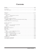
Contents Preface ......................................................................................................... 3–9 Introduction ............................................................................................................................... 3–9 About This Manual ................................................................................................................... 3–10 Chapter 1 ..........................................................................................
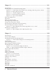
Chapter 2 .................................................................................................... 3–21 Introduction ............................................................................................................................. 3–21 Loading Paper for Standard Printing Mode .......................................................................... 3–22 Figure 2 - 1. Inside Paper Inlet, visible when looking inside the printer cabinet. ........ 3–22 Figure 2 - 2.
Config Key ................................................................................................................................. 3–35 Control Panel Menus ............................................................................................................... 3–36 Categories, Parameters and Selections ................................................................................... 3–36 Using Menus ..........................................................................................
Detect Distance ......................................................................................................................... 3–50 VFU Category (Vertical Format Units) ................................................................................... 3–51 VFU Enable ............................................................................................................................... 3–51 VT Channel (Vertical Tab Channel) .................................................................
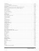
Busy Polarity .............................................................................................................................. 3–62 RTS Function ............................................................................................................................ 3–62 Robust Xon ............................................................................................................................... 3–62 Parallel I/O Category .........................................................
Appendix B: Specifications ......................................................................... 3–77 Industry and Agency Standards ............................................................................................... 3–77 Electro-Magnetic Emissions ..................................................................................................... 3–77 Electro-Magnetic Immunity .....................................................................................................
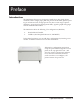
Preface Introduction The 2900 Impact Printers are designed to handle heavy duty, high volume workloads, with a straight paper path that provides unattended, jam-free printing of continuous forms, at high speeds. They have a wide range of printer emulations, network printer management ability, popular graphics languages and web administration utilities.
About This Manual Conventions We use the following conventions throughout this manual: Text that is placed in italics draws your attention to additional helpful information. Sometimes your attention is more particularly drawn by the use of this symbol. CAREFUL! This symbol marks information about actions that may damage the equipment or injure the user.
Chapter 1 Site Preparation Choosing a site for your printer is important because the environment affects your print quality. The best site for your printer is one that is protected from dirt and heavy dust, and has a moderate temperature and humidity range. In addition, the power source should be adequate for printer operation and protected from power surges.
Unpacking the Printer Unpacking your printer Instructions for unpacking your printer are located on the outside of the shipping container. After you have removed your printer from its container, store the shipping materials for possible later use. Repacking Repacking your printer for storage or shipping is the reverse order of unpacking. If shipping materials are needed, you can reorder them from your dealer.
Interface Connections Interface Connections and Powering Up Interface Connectors Properly secure the cable to the printer interface using the correct connectors. CAREFUL! Shielded I/O cables must be used on all installations to comply with regulatory requirements. Connecting the I/O After connecting each interface to your printer, run a print job from the Host Computer to verify proper function of the printer.
Powering Up Powering Up The power switch is located on the back of the printer, just above the 3-prong power plug connector. Figure 1 - 4. Power plug and on/off switch Step 1. Make sure the power is off by depressing the "0" side of the rocker power switch. Connect the power cord. Plug the power cord into a proper power outlet. Step 2. Turn the power on. The printer runs a self-test each time it is powered up to check the main processor and buffers for errors.
Paper System Components Paper System Paper System Components The Tractors, Ribbon Cartridge, Platen and Paper Iron are all parts of the paper system. The first two can be seen when the lid is raised. The Platen and Paper Iron are hidden inside the housing. Tractors shaft for tractors Ribbon support platform Ribbon Cartridge Figure 1 - 5.
Paper System Components Tractors The 2900 has two tractors to control paper movement, located on the left and right. A lever on each tractor keeps it locked in place on a horizontal shaft. To reposition a tractor, unlock the tractor and move it to the left or the right along the shaft. Repositioning is generally needed only when inserting a new form or size of paper. Tractors Open locking lever Figure 1 - 6.
Installing Ribbon Cartridge Installing the Ribbon Cartridge Step 1. Make sure the printer is Offline or power is off. Open the printer lid and remove the old ribbon by lifting it straight up off of the Ribbon Platform. Figure 1 - 7. Ribbon Cartridge Step 2.
Installing Ribbon Cartridge The front and rear panels of the ribbon shield Figure 1 - 9. Ribbon Shield Panels The ribbon has been carefully positioned between the two panels of the ribbon shield.
Control Panel Components Control Panel Components The Control Panel is located on the right front top of the printer housing. It is used to program and direct most printer functions. Red LED Indicator Green LED Indicabeeper } 32-character Figure 1 - 10. Control Panel LED Indicators The green ONLINE indicator illuminates whenever there is power to the printer, and the printer is Online. The red FAULT Indicator illuminates whenever an error or fault is detected.
Blank Page 1–20 Operator Manual
Chapter 2 Introduction This chapter covers how to load the paper and to set the print gap. It also covers how to create saveable configuration settings for your own pre-printed forms. Your printer is designed to use a continuous sheet, sprocket-fed paper. It can handle: • Six-part forms (1 original and 5 copies) with a maximum thickness of .025" (0.6 mm). • Page widths of 2.5" to 18" (6.4 cm to 45.7 cm). Specific requirements for pre-printed forms are in Appendix C: Specifications.
Standard Printing Mode Loading Paper for Standard Printing Mode Step 1. Turn off the printer using the power switch on the back, or toggle the "Online" button on the Control Panel until the LCD shows "Offline". Step 2. Raise the printer lid and open the doors on both tractors. Figure 2 - 1. Inside Paper Inlet, visible when looking inside the printer cabinet. Step 3. Open the new box of paper. Remove the box top so that the paper can be pulled out freely.
Standard Printing Mode Figure 2 - 4. Column Alignment Scale Step 6. The Column Alignment Scale is on the top of the ribbon support platform. It is to be used for general guidance in horizontally aligning the form for each print job. The leftmost mark on the scale indicates the location of the first, or leftmost, printable character. Each successive tick mark indicates the location of additional 10 CPI characters.
Standard Printing Mode Fine-tuning the Column Alignment can be done in two ways: (1) Rotate the Horizontal Vernier Wheel, which is located on the right end of the shaft on which the tractors ride. Depending upon the direction the paper needs to move, you will rotate the wheel either upwards or downwards. (2) Use the Control Panel. Go Offline, choose Menu, then use the arrow keys to get to the Operator Menu. Press Enter. Use the arrow keys to get to Forms. Press Enter.
Print Gap Print Gap Adjustment The 2900 Auto-Gap feature automatically sets the correct print gap based on form thickness. Dedicated control panel keys also allow the print gap to be adjusted for darker or lighter print based on user preference. For ease of paper loading, the print gap is set to its widest position while the printer is not printing. The Auto-Gap feature is automatically initiated under the following conditions: 1.
Print Gap Step 3 – Create the Profile Select the Detect Parameter in the Print Gap Category of the Operator Menu. Press Menu => up arrow until Detect shows => Enter. This will cause the printer to move down the form in 1/6 inch increments, performing a print gap detection operation at each increment. Note that this operation will take approximately five to six minutes for an 11 inch form.
Print Gap After unlocking the Print Gap keys: Press one of the Print Gap keys on the Control Panel. This activates the Print Gap adjustment display. Look at the Control Panel. The upper right region of the LCD shows a number 1 corresponding to the optimal print gap determined by the detection process. The lower right region displays a “fine tuning” offset which is added to the detected print gap to set the actual gap number.
Manually Setting Print Gap The lower left region of the LCD provides a graphical indication of the adjustment being made. There is a 5 second time-out: if no keys are pressed the control panel display will revert to the prior menu and display. The Print Gap keys may be pressed while printing is in progress, allowing the operator to modify the print gap and immediately observe the effect it has upon print appearance. Figure 2 - 8. Typical display when adjusting Print Gap Step 2.
Chapter 3 Introduction In this chapter you will learn how to use the Control Panel, how to navigate the menus, and how to select and store parameter values as part of a configuration. You will also learn how to obtain printouts that show all available parameters, current configuration settings, and technical information like accumulated running time and operating thresholds. Let's begin with looking at the control panel display, and at each of the keys.
Control Panel Display The Display During Normal Operation During normal operation, the top line of the display indicates the current state of the printer, such as Online, Offline, or a fault message. The second line of the display will indicate which of 10 saved configurations is currently loaded. Each of the configurations can be assigned a unique name and any of the configurations can be designated as the power up configuration. By default, this line will display Config 1.
Control Panel Display Indicator Paper Weight and Hammer Impact (blank) hammer impact setting is “Normal” paper weight setting is “Light” H hammer impact setting is “Normal” paper weight setting is “Heavy” – hammer impact setting is “High” paper weight setting is “Light” H hammer impact setting is “High” paper weight setting is “Heavy” Table 3 - 1 Paper Weight & Hammer Impact Indicator The Display When In A Menu When a menu is selected, the top line of the display shows which menu, category, or pa
Control Panel Key Functions Control Panel Key Functions Online Key This key toggles the printer between Online and Offline states, or exits from the menu directly to an Online state. When the printer is Online, the indicator will light. In the Offline state, you may change parameter selections, load paper, and so on. LF Key (Line Feed) This key advances the paper one line. It performs the same function whether the printer is Online or Offline. You may auto-repeat this command by holding down the key.
Control Panel Key Functions FF Key (Form Feed) continued When In a Fault Condition Pressing the FF Key while in a Fault Condition advances the paper one form. No data prints, and the Top of Form position is maintained. This allows the use of the FF Key to advance paper while in a Paper Out condition, without printing any buffered data. TOF Key (Top of Form) When you load paper, you line up the top of your form (usually the perforation) with the indicated position on the tractor (see Figure 2-6).
Control Panel Key Functions Enter Key In any of the menus, this key allows you to enter a lower level, to assign a selection to a parameter, or to perform a menu function. When the printer is in a Paper Out Fault condition, and the PrntEOF parameter is set to Off, pressing the Enter Key allows printing to the end of the current form. When PrntEOF is set to On, the printer automatically prints to the end of the current form.
Control Panel Key Functions Clear Key continued Config Key Offline This is a “shortcut” to the Load Configurations menu item (see later in chapter), allowing you to enter a menu where any of ten saved configurations can be loaded into the Current Configuration. Use the Up and Down Arrow keys to scroll through the configurations. Pressing the Enter key loads the one you choose.
Using Menus Control Panel Menus This section discusses the menus and how to access and select values from them for formatting documents, controlling print operations, or testing the printer. The four main menus are Operator, Config, Test, and Help. Categories, Parameters and Selections Within the Operator, Config, and Test menus, there are a number of categories. Within some categories there are sub-categories. Within each of these categories or sub-categories is a list of parameters.
Using Menus The name of the configuration displays on the lower line. In this state, the only keys that respond are: • • • • • • • Up and Down Arrows LF FF Clear View Online Print Gap (+ & - ) When the printer is Offline, no light is on and the display reads: In the Offline state, pressing the Menu key gives you access to the first level of the menu system.
Changing Form Length Example: Changing Form Length Using the Menu System If you wanted to change the Form Length from the default of 66 lines to 65 lines, this is how you do it: 1. Make sure your printer is in an Offline state. If it's not, toggle the Online key. 2. Press the Menu key. The display reads: 3. Press Enter to select the Operator menu and press the down arrow key until you see Forms. The display reads: 4. Press the Enter key to select Forms.
Print Selections Report 7. Press the Enter key. The Form Length is set to 65, and an asterisk appears beside the number. Exit the menu mode by pressing the Clear key. It's helpful to remember that at any time, you may leave a menu in one of two ways. • • Press the Clear key to leave Menu Mode and remain Offline. Toggle the Online key to leave Menu Mode and return the printer to Online.
Operator Menu ⇒ Font Operator Menu 1. Toggle the Online key once or twice to clear the display and put the printer Offline. Offline should be displayed and the green light should be off. 2. Press the Menu key. 3. Use the Up or Down arrow keys until you see Operator Menu on the display. 4. Press Enter. 5. Use one of the arrow keys until the desired category appears; press the Menu key if you need to back up a level.
Operator Menu ⇒ Font Ser/Par Character Set This parameter allows you to select a character set that occupies locations Hex 80 through FF used by emulations attached to the Parallel, Serial, and LAN ports. The default is Code Page 437: The details of the character sets can be found in the Line Printer Applications Manual.
Operator Menu ⇒ Font Ser/Par Style This parameter allows you to select the font style used by emulations attached to the Parallel, Serial, and LAN port. For emulations that support downloaded fonts, you can use this parameter to select the download font. The default option selection is DP.
Operator Menu ⇒ Font Forms Category This category is used for setting up the specifics for your individual forms. Use the Arrow and Enter keys to select Menu => Operator Menu => Forms => to get here. Length (lines) If you wish to define the length of your form in lines, you may select a form length from 1 to 255. The default option is 66. Length (inches) If you wish to define the length of your form in inches, you may select a form length from 0.1 to 25.5 inches. The default option is 11.0 inches.
Operator Menu ⇒ Forms Left Margin You can place the left margin at any column number across the page, using parameter options 1 to 272. The range of options for this parameter depends on the CPI setting. Column 1 is the default option. The left margin must be less than or equal to the right margin. Right Margin You can place the right margin at any column number across the page. As with Left Margin, the range of this value depends on the CPI. Column 136 is the default option.
Operator Menu ⇒ Forms Print to EOF (End Of Form) Continued If Print to EOF is ON: The printer automatically prints to the end of the form then stops. The display reads Paper Out, the alarm sounds, and the FAULT indicator illuminates. At this point you can load the machine with more paper. After you load paper, adjust the top-of-form location and make sure the paper is feeding correctly.
Operator Menu ⇒ Forms Eject Delay This parameter specifies the timeout interval in seconds (after which printing will resume) when Quick Access is Enabled while the printer is Online. The default is 30 seconds. Impact This parameter has three options: Auto, which is the default, Normal, and High. Paper Weight The Paper Weight parameter defines the “paper moves” — how the paper motion and printing work according to the thickness of the paper.
Operator Menu ⇒ Forms If the Ribbon Monitor Fault occurs, and is cleared without the ribbon life threshold being increased or the ribbon count reset to zero, the “Replace Ribbon” message will reappear approximately every one million characters until one of these operations is performed. This message will also appear upon powerup if the ribbon count is above the threshold at that time. RibnMon Thresh This parameter sets the ribbon life threshold of the Ribbon Monitor feature.
Operator Menu ⇒ Print Gap Perf Skip This parameter will enable the automatic perforation skip feature that will cause the print gap to automatically increase significantly between the last line printed on the current form and the first line printed on the next form. This feature is useful when using heavy forms that have a large perforation “tent” that can get hung up in the print station. The options for this parameter are Enabled and Disabled (default).
Operator Menu ⇒ Print Gap Fine-Tuning the Print Gap Manually The lower right region of the LCD shows a number2 corresponding to the current gap separating the hammer impactors from the platen. Press the "+" or "-" Print Gap key to roughly match the setting to the kind of paper that is loaded. This number will get larger or smaller respectively. The range of allowed change is unrestricted over the complete gap range.
Operator Menu ⇒ Print Gap Creating a Gap Zone Profile A Gap Zone Profile is created automatically in four steps: Step 1 – Load the Form Load the form for which the profile will be generated; doublecheck the Top of Form position with Form Length. Step 2 – Set Profile Mode Set the Mode Parameter to Profile. Step 3 – Create the Profile Select the Detect parameter. Note that this operation will take approximately five to six minutes for an 11 inch form.
Operator Menu ⇒ VFU VFU Category (Vertical Format Units) Use the Arrow and Enter keys to select Menu => Operator Menu => VFU to get here. VFU Enable A Vertical Format Unit is a means for loading sets of vertical tabs. These vertical tabs define various parameters of a form and apply only to the emulations which make explicit use of the VFU channels. Setting this to Enabled causes the printer to use the last loaded EVFU instead of using the Form Length, Top Margin, and Bottom Margin settings.
Config Menu ⇒ Printer Config Menu Following are explanations of each category and parameter in the Config Menu. For all available options under each parameter below, consult the Help Menu printout. The categories here are Printer, Codes, Graphics, Configurations, Serial I/O, Parallel I/O, IntelliFilter, and when the options are installed, Twinax/Coax and IPDS. Printer Category Use the Arrow and Enter keys to select Menu => Config Menu => Printer to get here.
Config Menu ⇒ Printer Style3: Control codes and spaces are printed in hexadecimal format. ASCII characters are printed as is and escape sequences force a new line. IO Hold This parameter allows you to set the amount of time the printer remains locked onto the I/O on which it is receiving data after data transmission stops. You can set this to be 5 - 600 seconds. Default is 30 seconds.
Config Menu ⇒ Printer Beeper Mode When a fault event occurs, the beeper will sound. There are two options: Single or Persistent. In the Single mode, each fault event will cause the fault alert beeper to produce just one short-duration audio tone and then to remain silent. In the Persistent mode, a fault event will cause the fault alert beeper to periodically produce a short-duration audio tone that cycles approximately once per second and will persist until the operator clears the fault.
Config Menu ⇒ Codes Codes Category In this category are choices that allow you to determine the printer’s response to certain conditions and to assign values to parameters that are used by other commands or escape sequences. Use the Arrow and Enter keys to select Menu => Config Menu => Codes to get here. Auto LF (Line Feed) Auto LF causes the printer to perform a Line Feed each time it receives a Carriage Return Control Code.
Config Menu ⇒ Codes Print on CR This parameter is intended for use by customers whose applications embolden characters by using a CR-only method to selectively reprint all or parts of a line.
Config Menu ⇒ Codes Code 7F This parameter allows you to dictate how the printer will react when it receives a Hexadecimal code 7F. The default value depends on the emulation. (See the Emulation Parameter, presented earlier in this chapter.) Ignore: Delete Char: Delete Buffer: Space: Fill: The code is ignored. The previous character is deleted. The previous characters on the current print line are deleted. A Space character is substituted. A Fill character is substituted.
Config Menu ⇒ Configurations Configurations Category The 6300 Series printer can save up to ten personalized configurations, so you don't have to recreate configurations you use frequently. In addition, each configuration you save can be tagged with a label of up to 15 characters. When you first receive your printer, each label is a generic "CONFIG" followed by a number 1 through 10. Use the Arrow and Enter keys to select Menu => Config Menu => Configurations to get here.
Config Menu ⇒ Configurations How to label a configuration slot • Make sure the printer is Offline. • Press the Menu key to enter Menu mode. • Use the Up and Down Arrow keys to get to the Config menu, and then press Enter. • Use the Up and Down Arrow keys until the display reads Configurations, then press Enter. • Use the Up and Down Arrow keys until you see Config n label, where n is the number of the configuration you want to label (1-10). Press Enter. • A cursor appears underneath the first letter (C).
Config Menu ⇒ Serial I/O Serial I/O Category Serial Interface is a style of host computer-to-printer I/O communications. It requires certain parameters to be properly set in order for the printer and host computer to communicate. Use the Arrow and Enter keys to select Menu => Config Menu => Serial I/O to get here. Baud The Baud parameter allows the user to set up the printer to receive data at different transmission speeds. The baud rate must be the same value at both ends of the communication line.
Config Menu ⇒ Serial I/O Status Enquiry When this parameter is enabled, the host may send an enquiry packet to the printer requesting status. The printer will then send back a 1 byte packet denoting the status of the printer. If this option is set to OFF (the default), no packet will be sent back. The Status Enquiry feature may be enabled in conjunction with any other protocol. When enabled and the host sends an ENQ character, the printer responds by sending a printer status byte.
Config Menu ⇒ Serial I/O DTR Function continued... Offline: When this option is active, the DTR Line is used to signal only that the printer is Online or Offline. Unlike the Busy option, the Offline option will not interfere with operation of the Xon/Xoff Communication Protocol. Power: When this option is active, the DTR Line is used to signal the host that the printer is powered up.
Config Menu ⇒ Parallel I/O Parallel I/O Category The Parallel Category on your printer has three parameters that can be changed according to user needs. Use the Arrow and Enter keys to select Menu => Config Menu => Parallel I/O to get here. POPC (Print On Paper Command) The POPC parameter can be set up so that each time a paper advance command is received (such as a Line Feed, Form Feed, or Vertical Tab), any data currently held in the buffer will be printed before the command is carried out.
Config Menu ⇒ Intellifilter Intellifilter Category Use the Arrow and Enter keys to select Menu => Config Menu => Intellifilter to get here. Intellifilter is a programmable feature, standard on TallyGenicom line printers. Without having to touch an otherwise well-working host system, Intellifilter permits users to free their systems from hard coded dependence on a specific printer that is no longer maintainable, or able to meet the demands of the application.
TCP/IP Menu TCP/IP Menu (LAN Interface Only) The TCP/IP Menu only appears if a TCP/IP LAN network interface card is installed in the printer. IP Addr Category This lets you to set up the four OCTETS of the IP Address. Use the Arrow and Enter keys to select Menu => TCP/IP => IP Addr to get here. Parameter IP OCTET 1 IP OCTET 2 IP OCTET 3 IP OCTET 4 Option 0-255 0-255 0-255 0-255 Gateway Category This lets you to set the four OCTETS of the Gateway.
TCP/IP Menu ⇒ Subnet Subnet Category This option allows you to set up the four OCTETS of the Subnet mask. Use the Arrow and Enter keys to select Menu => TCP/IP => Subnet to get here. Parameter IP OCTET 1 IP OCTET 2 IP OCTET 3 IP OCTET 4 Option 0-255 0-255 0-255 0-255 Make sure that the LAN cable is attached when the printer is powered on. If it is not, attach the cable and cycle power on the printer.
TestMenu ⇒ Pattern Test Menu In TEST Menu you will find diagnostic test print patterns used to check printer functions and a parameter that allows you to control paper motion sensing. Use the Up and Down Arrow keys to scroll to the desired selection. Pattern Category The Pattern Category has a series of printer self-tests which have predefined patterns used to test the basic printer functions.
Test Menu ⇒ Fault Override Fault Override Category This category deals with the configuration of fault information from the Engine Manager and the Control Processor. If the option is set to On, then the fault is overridden and won't be reported on the panel. If the option is set to Off, then the override is disabled and the fault is reported if it occurs. Use the Arrow and Enter keys to select Menu => Test Menu => Fault Override to get here.
Help Menu Help Menu There are no categories in this menu. Its purpose is to allow the user to print out a list of all of the selected options in a single report. See page 3-45 for how to do this. This graphic summarizes navigation through the menus, categories, and options of the control panel.
Blank Page 3–70 Operator Manual
Appendix A: Troubleshooting Introduction This chapter deals with troubleshooting problems on a 6300 Series printer. Messages that indicate printer faults and errors are explained and corrective action given. The few paper handling and print quality problems that may occur are also explained. Messages Messages on the Control Panel Display report both normal operation and fault situations.
Error Messages Step 4. If any other faults appear on the display after you have corrected the original problem, go back to Step 1 and perform required corrective actions for the new problem. Otherwise place the printer back Online and test it during normal print operations. Table A - 1. Display Messages MESSAGE ATTENTION Bad Packet Explanation and Corrective Action Explanation: Corrective Action: The host has sent the Bell Command. Corrective action depends on the reason the Bell Command was sent.
Error Messages Graphic Check Explanation: This message indicates that the printer has received an unprintable graphic. This message only appears if the Set Graphic Error Action Command has been set properly. HammerTime HammerVoltage1 HammerVoltage2 Corrective Action: Clear the message (Clear key), then place the printer back Online. Confirm with host why Graphic check message was sent. Explanation: The software controlling the print hammer timing has detected an internal inconsistency.
Error Messages Offline Data In Explanation: The printer is in Offline condition and nonprinted data is in the buffer. Corrective Action: There is no corrective action required. Under normal conditions, the printer continues to print when it is placed back Online. If you do not want the buffered data to print, enter the Clear menu by depressing the Clear key before going back Online and select the Clear Buffers entry to Offline Dump On Explanation: clear the buffered data.
Error Messages Ribbon Fault Explanation: The Ribbon Fault Detector is not reading any movement in the printer Corrective Action: ink-ribbon. Depress the Clear key and try to print again. If the fault returns, try to turn the Ribbon Knob. If the Ribbon Knob will not turn, check to see if the ribbon is caught on the hammer bank or one of the other mechanisms through which the ribbon moves. If the Ribbon Knob does not turn and the ribbon is not caught somewhere, install a new ribbon cartridge.
Paper Problems Table A - 2. Paper/Printing Corrective Action Problem Cause Corrective Action The paper holes are wider than normal after passing through the tractors. Horizontal paper tension is too tight. Unlock and readjust the tractors so that the paper holes line up evenly with the tractor pins. Printed characters on heavyweight or multi-part paper are smeared. The Print Gap is too tight.
Appendix B: Specifications Industry and Agency Standards The 2900 printer is designed to meet the requirements of several industry and government agency standards.
Industry and Agency Standards Physical Configurations Weight 115.4 lbs. Dimensions Width: 28.3 inches Height: 13.0 inches Depth: 14.4 inches Depth with paper exit guide assembly: 23.4 inches Preventive Maintenance This printer is designed to eliminate the requirement of scheduled maintenance procedures, such as alignment, adjustment, or lubrication. Preventive maintenance is limited to periodic cleaning. Dust and paper fibers should be removed periodically with a soft cloth and brush or a vacuum cleaner.
Environment Cooling System Cooling system malfunctions are detected and a failure will result in shuttle motion, paper motion, and printing functions being inhibited. The malfunction Hammer Voltage1 will be reported on the control panel display. Acoustics The Sound Power Level is a 9 position average, per ISO 7779. The Sound Pressure Level is a 4 position average, per ISO 9296. Sound Pressure Level Sound Power Level 55 dB(A) 7.0 Bel Power Supply The printer requires single phase, 47 to 63 Hz.
Emulations and Fonts Emulations Emulations available on the 2900 Series: Epson DFX-9000, IBM Proprinter III XL, MTPL Characters Per Inch Seven basic Characters Per Inch (CPI) settings are available through the Control Panel. They include 10, 12, 13.33, 15, 16.67, 17.14, and 20. These character matrices can be doubled to produce 5, 6, 6.67, 7.5, 8.33, and 8.57 CPI. In some emulations the availability of certain CPIs is restricted. Some emulations provide proportional spacing and justification features.
Fonts, Languages and Characters Standard Languages and Character Sets There are two ways to select a language or character set. One method is by substituting certain characters in the lower half of the character set, such as # $ @ [ \ ] ^ ` { | } and ~. This can be done by using the control panel Language selection, or through the emulation. The language substitutions available through the emulation differ by emulation.
Configurations, Paper and Speed Nonvolatile Memory Your printer stores up to 10 printer configurations in nonvolatile memory. Paper Description The printer uses continuous, sprocket-fed type paper, 2.5 inches (64 mm) to 18 inches (457 mm) outside width and 3.0 inches (76 mm) to 12.0 inches (305 mm) in length. One- to six-part paper may be used with a maximum thickness of .025 inches (0.64 mm). (Reference specifications: ISO 2784, DIN 9771 and DIN 6721.
Blank Page Appendix B: Specifications B–83
4500 Daly Drive, Suite 100 Chantilly, VA 20151 T 703.833.8700 F 703.222.7629 www.tallygenicom.