Solar Kit Installation Instructions THIS PRODUCT MUST BE INSTALLED IN ACCORDANCE WITH THE APPLICABLE INSTALLATION CODE BY A PERSON FAMILIAR WITH THE CONSTRUCTION AND OPERATION OF THE PRODUCT AND THE HAZARDS INVOLVED CE PRODUIT DOIT ÊTRE INSTALLÉ SELON LE CODE D’INSTALLATION PERTINENT, PAR UNE PERSONNE QUI CONNAÎT BIEN LES PRODUIT ET SON FONCTIONNEMENT AINSI QUE LES RISQUES INHÉRENTS I. Introduction This manual is for the installation of solar kits SLR-80-84 and SLR-120-84.
Solar Kit Installation Instructions Package 5: SLR-80-84 and SLR-120-84 Qty. Part Number Description 2 1 2 2 6 20 ft 6 68594 68681 42855 42847 67547 19678 67545 1 1 68689 24701 1 1 68680 24705 42 Ah batteries Solar Controller 10-24 Screws for mounting Solar Controller 10-24 Nuts for mounting Solar Controller Terminal - Spade/Fork, #6 Tab, 12-10 AWG Cable, Solar - 12AWG, Tray Cable, 2C, Black-Red Terminal - Ring , 0.
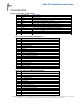
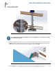
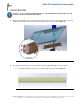
Solar Kit Installation Instructions III. Tower Enclosure Installation 1. Remove the tower’s rear bottom access panel by removing tamper-proof screws. 2. Install one 3/4” leveling nut and one washer on each anchor bolt 2 ½” - 3 ½” above grade and verify that nuts are level (0° pitch) as shown in Figure 1. Figure 1. Tower Enclosure Installation 3. Install the tower onto the leveling bolts with the emergency phone opening oriented in the direction desired. Install the second set of nuts and washers.
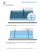
Solar Kit Installation Instructions Figure 3. Mounting rail fastened to the panel frame 4. Attach the clips to the rails so that the flanged end containing the slots on the clips are facing the center of the panel as shown in Figure 4. Figure 4. Orientation of clips with reference to solar panel 5. Attach the clips to the rails. In each of the mounting holes, use a 5/16 - 18 x 3/4” bolt and flat washer on one side and a flat washer, lock washer and nut on the other as shown in Figures 5 & 6.
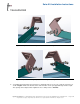
Solar Kit Installation Instructions Figure 5. Exploded view of left clip attached to the left mounting rail Figure 6. Exploded view of right clip attached to the right mounting rail 6. To install the bucket brackets, thread each hose clamp through one of the sets of narrow center holes as shown in Figure 7. Place the buckets at the desired location on the pole approximately 18 inches apart. The spacing can be adjusted later. Tighten the hose clamp screws to 70 in-lbs. Copyright 2013 Talk-A-Phone Co.
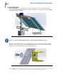
Solar Kit Installation Instructions Figure 7. Mounting buckets attached to the pole using hose clamps For countries in the northern hemisphere (U.S.A., Canada, Mexico) all solar panels should be installed facing south. 7. Place the solar panel assembly so the slots on the clips line up with holes inside of the bucket as shown in Figure 8. Bolt the clips to the bucket using 5/16 - 18 x 3/4” hex cap bolt and flat washer on one side, and a washer, lock washer and nut on the other.
Solar Kit Installation Instructions 8. Refer to Appendix A for correct tilt angle according to geographic location. To adjust the tilt angle loosen the bolts holding the mounting rails to the clips and adjust the tilt of the panel as shown in Figure 9. Retighten the bolts to 12 ft-lbs. Figure 9. Panel tilt angle reference Steps 9 – 12 are for solar kit SLR-80-84 only. For solar kit SLR-120-84, skip to step 13. 9.
Solar Kit Installation Instructions 10. To assemble the support rails, fit the smaller inner channel inside the larger outer channel so that the mounting holes on the flanges are opposite one another. Slide the channels to obtain the correct length determined by the panel tilt angle. Secure the support rails together at the desired length using a 1/4-20 x 3/4” hex bolt, lock washer, and flat washer on one side, and a flat washer and hex nut on the other side (2 per rail assembly) as shown in Figure 11.
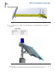
Solar Kit Installation Instructions Figure 13. Secure support rails to panel mounting rail and lower bucket bracket 12. Once all adjustments are complete, ensure that all hardware is adequately tightened to specifications listed below. Figure 14. Assembled view of SLR-80-84 (shown on ETP-MTE-WP) Copyright 2013 Talk-A-Phone Co. • 7530 North Natchez Avenue • Niles, Illinois 60714 • Phone 773.539.1100 • info@talkaphone.com • www.talkaphone.com. All specifications are subject to change without notice.
Solar Kit Installation Instructions Steps 13 – 18 are for solar kit SLR-120-84 only. For solar kit SLR-80-84 complete steps 9-12 and proceed to section V: Mechanical Installation 13. Bolt the remaining two clips to the lower bucket using the 5/16-18 x 3/4" bolt and flat washer on one end and a flat washer with a lock washer under the nut on the other end as shown in Figure 15. Figure 15. Installation of the clips to the lower bucket 14.
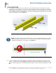
Solar Kit Installation Instructions b. For optimum tilt angles of 50-60º, cut and discard the section 10 inches from the right as shown in Figure 17. Figure 17. Support rail length for a solar panel with a tilt angle of 50-60º c. For an optimum tilt angle of 65º, cut and discard the section 6 inches from the right as shown in Figure 18. Figure 18.
Solar Kit Installation Instructions Figure 19. Support rail installation for a solar panel with a tilt angle of 45º Figure 20. Support rail installation for a solar panel with a tilt angle of 50º Copyright 2013 Talk-A-Phone Co. • 7530 North Natchez Avenue • Niles, Illinois 60714 • Phone 773.539.1100 • info@talkaphone.com • www.talkaphone.com. All specifications are subject to change without notice. Talk-A-Phone is a registered trademark of Talk-A-Phone Co. All rights reserved.
Solar Kit Installation Instructions Figure 21. Support rail installation for a solar panel with a tilt angle of 55º Figure 22. Support rail installation for a solar panel with a tilt angle of 60º Copyright 2013 Talk-A-Phone Co. • 7530 North Natchez Avenue • Niles, Illinois 60714 • Phone 773.539.1100 • info@talkaphone.com • www.talkaphone.com. All specifications are subject to change without notice. Talk-A-Phone is a registered trademark of Talk-A-Phone Co. All rights reserved.
Solar Kit Installation Instructions Figure 23. Support rail installation for a solar panel with a tilt angle of 65º 16. Once the adjustments are complete, tighten all 5/16” hardware to 12 ft-lbs as shown in Figure 24. Figure 24. Assembled view of SLR-120-84 (shown on ETP-MTE-WP) Copyright 2013 Talk-A-Phone Co. • 7530 North Natchez Avenue • Niles, Illinois 60714 • Phone 773.539.1100 • info@talkaphone.com • www.talkaphone.com. All specifications are subject to change without notice.
Solar Kit Installation Instructions V. Mechanical Installation 1. Install the LED light board above the phone opening. To install the polycarbonate light cover that protects the LED light assembly from the inside, peel the protective film off the light cover and fit it onto the studs inside the tower. Slide the LED board over the studs with the LEDs facing down. The built-in spacers will keep the LEDs from resting on the acrylic window. Tighten down using the enclosed #6 nuts.
Solar Kit Installation Instructions b. Fasten the LED Blue Light to the base plate on top of the pole with three (3) tamperproof screws. Feed the power cord and control wires through the pole mount and the enclosure mount. c. Feed the power cable and the antenna cable through the tower enclosure all the way to the bottom of the tower. Surplus cable is used to connect the two batteries. d. Fasten the pole mount enclosure with the solar panel and antenna attached, to the tower e.
Solar Kit Installation Instructions a. Fasten the LED Blue Light to the base plate with three (3) tamperproof screws inside the Blue Light housing at the top of the tower. Feed the power cord and control wires through the tower enclosure. b. Feed the power cable and the antenna cable through the two wire routing clips and into the hole beneath the clips to run those cables into the tower enclosure all the way to the bottom. Extra cable is used to connect the two batteries. c.
Solar Kit Installation Instructions Figure 27. Connecting the power cable to the solar panel junction box 2. Connect the power cable from the solar panel to the “SOLAR” terminals on the solar controller. Do not discard excess wire. Refer to the wiring diagram as shown in Figure 28. 3. Connect the batteries in parallel to the “BATTERY” terminals on the solar controller using the excess power cable. Crimp-on connectors are included for the batteries.
Solar Kit Installation Instructions Figure 28. Solar system wiring schematic Copyright 2013 Talk-A-Phone Co. • 7530 North Natchez Avenue • Niles, Illinois 60714 • Phone 773.539.1100 • info@talkaphone.com • www.talkaphone.com. All specifications are subject to change without notice. Talk-A-Phone is a registered trademark of Talk-A-Phone Co. All rights reserved.
Solar Kit Installation Instructions 4. The LED Blue Light (as shown in Figure 29) and LED Panel Light power wires should be connected to the “LOAD” terminals on the controller. Connect to LOAD Terminals on the Solar Controller Figure 29. Electrical Connections to the ETP-EL 12/24 LED Blue Light NOTE: TOWER PTS SOLAR is shipped with ETP-EL12/24 Series Blue Light in Low Power Mode instead of default power mode as shown in Figure 30. For Solar applications the Blue Light must operate in Low Power Mode.
Solar Kit Installation Instructions 5. If installing an ETP-CI, connect the antenna cable to the cellular interface. Cellular interfaces should be powered by the included DC/DC converter, which has battery ring terminals pre-connected. The cellular interface (through the DC/DC converter) should be connected directly to the battery. The DC-DC converter should be set to 7.5 VDC for the cellular interface device.
Solar Kit Installation Instructions Figure 31. ETP-MTE-WP with access panel removed, assembly overview (SLR-120-84) Copyright 2013 Talk-A-Phone Co. • 7530 North Natchez Avenue • Niles, Illinois 60714 • Phone 773.539.1100 • info@talkaphone.com • www.talkaphone.com. All specifications are subject to change without notice. Talk-A-Phone is a registered trademark of Talk-A-Phone Co. All rights reserved.
Solar Kit Installation Instructions Figure 32. ETP-MT/R OP SOLAR with access panel removed, assembly overview (SLR-120-84) Copyright 2013 Talk-A-Phone Co. • 7530 North Natchez Avenue • Niles, Illinois 60714 • Phone 773.539.1100 • info@talkaphone.com • www.talkaphone.com. All specifications are subject to change without notice. Talk-A-Phone is a registered trademark of Talk-A-Phone Co. All rights reserved.
Solar Kit Installation Instructions Appendix A: Solar Panel Optimum Tilt Angle Table Year-Round Non-Adjustable Installation ALABAMA Birmingham- AL Mobile-AL Montgomery-AL ALASKA Adak-AK Annette-AK Bethel-AK Gulkana-AK Homer-AK Juneau-AK King Salmon-AK Kodiak-AK Matanuska-AK McGrain-AK Summit-AK Yakutat-AK ARIZONA Phoenix-AZ Prescott-AZ Tucson-AZ Winslow-AZ Yuma-AZ ARKANSA Fort Smith-AR Little Rock-AR CALIFORNIA Alpine-CA Arcata-CA Arrowhead-CA Bakersfield-CA Blythe-CA Butler Valley Ranch-CA Carlsbad-CA Car
Solar Kit Installation Instructions MARYLAND Baltimore-MD Patuxent River-MD MASSACHUSETTS Blue Hill-MA Boston-MA MICHIGAN Alpena-MI Detroit-MI Flint-MI Grand Rapids-MI Houghton-MI Sault St. Marie-MI Traverse City-MI MINNESOTA Duluth-MN Interna'l Falls-MN Minn-St. Paul-MN Rochester-MN MISSISSIPPI Jackson-MS Meridian-MS MISSOURI Columbia-MO Kansas City-MO Springfield-MO St.