
Manual

ETP-GSM – Cellular Interface
Installation Instructions
Page 8 of 10 Rev. 12/16/2014
Copyright 2014 Talk-A-Phone Co. • 7530 North Natchez Avenue • Niles, Illinois 60714 • Phone 773.539.1100 • info@talkaphone.com • www.talkaphone.com.
All prices and specifications are subject to change without notice. Talk-A-Phone, Scream Alert, WEBS and WEBS Contact are registered trademarks of Talk-A-Phone Co. All rights reserved.
All other trademarks mentioned in this document or website are the property of their respective owners and does not imply or indicate any approval, endorsement, sponsorship, or affiliation
with such owners unless such approval, endorsement, sponsorship, or affiliation is expressly indicated.
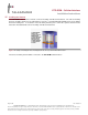
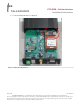
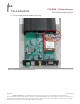
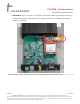
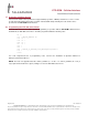
8. Flip the tray back to the closed position. Lock the SIM card holder by sliding the tray in the direction of
the arrow located on the tray. Figure 7 illustrates a SIM card locked into the SIM card holder.
Figure 7. SIM card installed and locked into the SIM card holder.
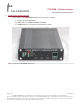
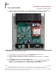
9. Carefully slide the electronic board back into the ETP-GSM Cellular Interface chassis.
10. Using the supplied Torx T10 L-Key, reinstall the Torx T10 screws.
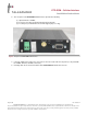
11. Connect the cable assembly from the remote-mounting omni-directional antenna to the CELLULAR
connector.
12. Connect the ETP-400 Series Phone to the PHONE-FXS port.
13. If a SOLAR KIT is used, connect the LOAD terminals of the solar controller to the appropriate polarity
markings on the 12VDC input terminal (i.e. POWER terminal) of the ETP-GSM Cellular Interface.
Otherwise, connect a 12VDC power source appropriately with respect to polarity.