
Instruction Manual

ETP-CDMA-V – Cellular Interface
Installation Instructions
Page 4 of 6 Rev. 12/12/2014
Copyright 2014 Talk-A-Phone Co. • 7530 North Natchez Avenue • Niles, Illinois 60714 • Phone 773.539.1100 • info@talkaphone.com • www.talkaphone.com.
All prices and specifications are subject to change without notice. Talk-A-Phone, Scream Alert, WEBS and WEBS Contact are registered trademarks of Talk-A-Phone Co. All rights reserved.
All other trademarks mentioned in this document or website are the property of their respective owners and does not imply or indicate any approval, endorsement, sponsorship, or affiliation
with such owners unless such approval, endorsement, sponsorship, or affiliation is expressly indicated.
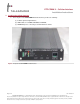
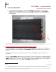
3. The rear panel of the ETP-CDMA-V Cellular Interface provides the following:
(1) Input terminal for 12VDC;
(2) Connector for remote-mounting omni-directional antenna;
(3) A serial port (for Talk-A-Phone Technical Support purposes only).
Figure 3. Rear panel of the ETP-CDMA-V Cellular Interface.
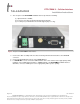
3. Connect the cable assembly from the remote-mounting omni-directional antenna to the CELLULAR
connector.
4. Connect the ETP-400 Series Phone to the PHONE-FXS port.
5. If a SOLAR KIT is used, connect the LOAD terminals of the solar controller to the appropriate polarity
markings on the 12VDC input terminal (i.e. POWER terminal) of the ETP-CDMA-V Cellular Interface.
Otherwise, connect a 12VDC power source appropriately with respect to polarity.