
Installation Sheet

- 11 -
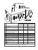
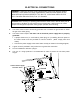
The dark square is the direction
the dipswitch should be set to.
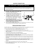
DIRECT INTAKE VENT SYSTEM
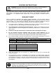
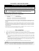
This water heater may be converted to a direct-vent (sealed combustion) appliance by installing
an adapter (Part No. 9007669005 (TM-DV50)) which will bring all required combustible air from
outside the building. When installing the direct-vent conversion kit, please follow all instructions
included with the kit.
• The water heater must be installed in a location where the proper amount of combustible
air will be available to it at all times without obstructions.
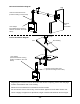
• If used as a direct-vent appliance, the water heater requires a 5” combustible air supply
pipe. The intake pipe must be sealed airtight.
• Air supply pipe can be made of ABS, PVC, galvanized steel, corrugated aluminum,
corrugated stainless steel or Category III stainless steel.
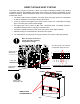
• Change the dipswitch settings to the direct-vent system. (See diagram below)
• Sidewall venting is recommended for the direct-vent system.
• The manufacturer recommends running the exhaust vent and the intake pipe parallel.
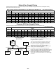
Direct-Vent
Conversion Kit
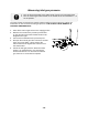
Make sure power to the unit is
turned OFF before changing
the dipswitch settings.
O
N
TMP1
TMP2
TMP3
MODE
DIRE
OUT
P-ALARM
MST
1 2 3 4 5 6 7 8
Lower Bank of Dipswitches
7-Seg LED
Lower bank of
dipswitches
Upper bank of
dipswitches
INTAKE
EXHAUST
DIRECT-VENT
CONVERSION KIT
LOUVER COVER PLATES