
Installation Sheet

- 38 -
H
e
a
t
e
r
Thermostat
Inlet
thermistor
Output
thermistor
Mixing
thermistor
BK
BK
BK
GFI
Trans-
former
1
23456
OFF
BR
BR
AC120V
10A
G
Ground
W
BK
BR
Ground
MAX button
MIN button
Increase button
Decrease button
Dip switch
(untouchable)
Air-fuel
ratio rod
Ground
Flame
rod
123456
OFF
1
23456
OFF
Burning lamp
MV
SV1
SV2
SV3
Communication
lamp (right)
Communication
lamp (left)
Indicator light for operation unit
in Easy link or Multi unit system
Dip switch
(Adjustable)
Dip switch (untouchable)
7 Seg LED
Pump test run
Error call
button
Remote
controller
port
Master
W
W
SLAVE
IN
SLAVE
OUT
Elect
rod
IG
Ground
Ground
Inlet
thermistor
Output
thermistor
Mixing
thermistor
BK
BK
BK
123456
OFF
Air-fuel
ratio rod
Ground
Flame
rod
MV
SV1
SV2
SV3
FM
Elect
rod
IG
Burning lamp
Heater
Heater
Heater
Heater
Heater
FM
port
Pump
port
Button to check
unit number
Priority SW
Alarm
contact
Draft switch
7
7
8
8
R
Y
G
W
BK
BR
R
O
Y
G
W
BK
BL
R
Y
G
W
BK
BR
R
O
Y
G
W
BK
BL
Water
Control
valve
Water
Control
valve
BK
BK
BK
BK
BK
BK
BK
BK
Y
G
O
O
G
Y
BK
BK
W
W
BL
BK
BK
R
R
BL
BL
GG
R
BL
Y
O
W
P
PP
PP
PP
P
Porpor-
tional
Valve
G
WR
BK
W
R
WR
BK
R
W
BL
LB
G
O
R
W
BK
Y
W
BK
W
BK
BL
LB
G
O
R
BK
W
BK
W
W
BK
BK
W
W
W
W
W
W
W
Porpor-
tional
Valve
Flow
Sensor
WR
BK
W
R
WR
BK
R
W
Hi-
limit
BL
O.H.C.F
BL
BL BL
BL
FM
R
BL
Y
O
W
BL
Hi-
limit
BL
O.H.C.F
BL
BL BL
BL
BL
Flow
Sensor
Left side unit
Right side unit
Dip switch
(untouchable)
MAX button
MIN button
Increase button
Decrease button
Fuse
box
BK
W
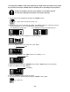
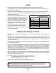
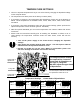
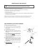
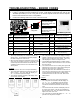
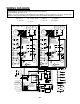
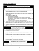
WIRING DIAGRAM
A wiring diagram is located on the inside front panel of the appliance.
Electrical Rating: 120 VAC, 60 Hz.
Note: If any of the original wiring supplied with this appliance must be replaced, it must be replaced with
appliance wiring material (180c) or its equivalent. Wires are available through the manufacturer.
BK:BLACK
P:PURPLE
LB:LIGHT BLUE
BL:BLUE
G;GREEN
Y:YELLOW
O:ORANGE
BR:BROWN