
Installation Sheet

- 25 -
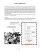
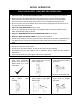
The dark squares indicate the direction
the dipswitches should be set to.
Easy Link Connection Procedures
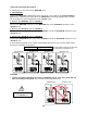
1. Choose one of your units as the “MASTER” unit.
2. “The MASTER”
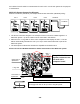
Locate the lower bank of dipswitches to the right of the 7-seg. LED on the central computer
board of the T-M50 that you select to be the “MASTER” unit. Change dipswitch No. 8 to “ON”.
Do not change any of the dipswitches on the “SLAVE” units.
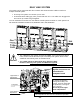
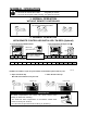
3. Between the “MASTER” and the “SLAVE-1”
Connect the “MASTER connector” of the “MASTER unit” to the “SLAVE IN connector” of the
“SLAVE-1” unit.
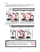
4. Between the “SLAVE-1” and the “SLAVE-2”
Connect the “SLAVE OUT connector” of the “SLAVE-1” unit to the “SLAVE IN connector” of the
“SLAVE-2” unit.
5. Between the “SLAVE-2” and the “SLAVE-3”
Connect the “SLAVE OUT connector” of the “SLAVE-2” unit to the “SLAVE IN connector” of the
“SLAVE-3” unit.
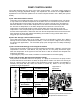
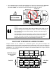
6. The numbering system of the T-M50 automatically allocates the unit # to each water heater
that is part of the Easy Link system.
CAUTION
• Unless you change dipswitch No. 8 of the “MASTER” unit to “ON”, the system will not
work as an Easy Link system. The units will work as individual units.
Master unit Unit # : 1
Slave units Unit# : 2, 3 and 4
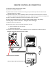
Communication cable
Connectors
Dipswitch
M
A
S
T
E
R
S
L
A
V
E
I
N
S
L
A
V
E
O
U
T
Connectors
Dipswitch
M
A
S
T
E
R
S
L
A
V
E
I
N
S
L
A
V
E
O
U
T
MASTER uni
t
SLAVE-1 unit
Wrong dipswitch setting
on the “MASTER
” unit
MASTER uni
t
SLAVE-1 unit SLAVE-2 unit SLAVE-3 unit
Communication cable
Connectors
Dipswitch
M
A
S
T
E
R
S
L
A
V
E
I
N
S
L
A
V
E
O
U
T
Connectors
Dipswitch
M
A
S
T
E
R
S
L
A
V
E
I
N
S
L
A
V
E
O
U
T
Connectors
Dipswitch
M
A
S
T
E
R
S
L
A
V
E
I
N
S
L
A
V
E
O
U
T
Connectors
Dipswitch
M
A
S
T
E
R
S
L
A
V
E
I
N
S
L
A
V
E
O
U
T