
Installation Guide


42 Page
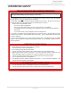
(A) 540P model computer board
Installaon
Installaon Manual
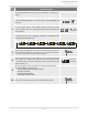
NOTE: The dark squares indicate the correct position of the DIP switches.
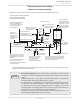
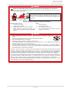
(B) Basic diagram of connections between the Easy-Link System units
PARENT
Communicaon cable
Connectors
Middle bank of
DIP switches
OFF
ON
1
1
12
2
2
PARENT
PARENT
PARENT
1
2
3
4
5
6
Connectors Connectors Connectors
OFF
ON
1
2
3
4
5
6
OFF
ON
1
2
3
4
5
6
Lower bank of
DIP switches
Lower bank of
DIP switches
Lower bank of
DIP switches
1
2
3
4
5
6
OFF
ON
PARENT UNIT
540P
CHILD UNIT
540
CHILD UNIT
540
CHILD UNIT
540
Built-in
or
remote
controller
Easy-Link
connector is
a label.
Middle bank of DIP switches
Upper bank of DIP switches
Lower bank of DIP switches
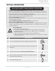
WARNING
To change the DIP switch settings for the Easy-Link System, locate
the middle bank of DIP switches at the upper left of the computer
board of 540P.
DO NOT adjust any other DIP switches .
Turn off the power supply to the water heater before changing the
DIP switch settings.
Failure to observe this warning could result in carbon monoxide poi-
soning or death.