
Installation Sheet


41 Page
EASY-LINK SYSTEM
The 540P model water heater can be connected to 540 models as only a PARENT unit in an Easy-
Link System.
The Easy-Link System allows up to 4 units to manifold together with communication cables.
In the Easy-Link System, one unit must be designated as a PARENT unit by changing one
of its DIP switch settings. The other units are CHILD units. The 540P model must be a
PARENT unit and cannot be a CHILD unit. (The 540 model can be either a PARENT unit
or a CHILD unit.)
Only one 540P can be installed in an Easy-Link System.
A communication cable (gray color) comes with each 540 model.
You can manifold from 2 to 4 units. A 4-unit system has full automatic modulation between
13,000 BTU/h (Propane) or 15,000 BTU/h (Natural gas)to 796,000 BTU/h.
Type of unit Model
Allocated No.
from controller
PARENT 540P 1
540 2,3,4*
*Each CHILD unit is allocated the above num-
ber from controller, which indicates on the
display of the controller on the unit. (Refer
to p. 65.)
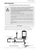
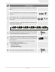
Hot Out
Gas In
Cold In
Return
Line
-Easy-Link connecon procedures for 540P & 540 models-
1. Make sure the power to the heaters are off.
2. Verify the DIP switch set temperatures of all units within the system. Every single water heater
must be set to the same set temperature. If a remote controller is used, it should be installed to the
“PARENT” unit. The remote will set the temperature for the entire system. When the 540P model is
the “PARENT” unit, the only controller that can be used is the 100276687 (TM-RE43).
3. Select 540P unit to be the “PARENT” unit. The “PARENT” unit should be one of the end units.
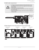
4. “PARENT” unit:
On the 540P that you select to be the “PARENT” unit, locate the three banks of DIP switches at the
upper left of the computer board. Change DIP switch No. 1 on the middle bank of DIP switches to
the ON position. See the computer board diagram as shown on the next page. Do not change any DIP
switches on any of the “CHILD” units.
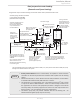
5. Between the “PARENT” and the “CHILD-1” units:
Connect the “PARENT” connector of the “PARENT” unit to the “1” connector of the “CHILD-1” unit
using the supplied linking cable.
6. Between the “CHILD-1” and the “CHILD-2” units:
Connect the “2” connector of the “CHILD-1” unit to the “1” connector of the “CHILD-2” unit.
7. Between the “CHILD-2” and the “CHILD-3” units:
Connect the “2” connector of the “CHILD-2” unit to the “1” connector of the “CHILD-3” unit.
8. Verify that all cables are connected like the diagram on the next page (B).
9. Turn on power to the “PARENT” unit.
Turn on “CHILD-1”. When the (remote and/or built-in) controller displays a number, turn on “CHILD-2”.
When the (remote and/or temperature) controller displays a number, turn on “CHILD-3”.
Make sure the (remote and/or temperature) controller display the unit #. The numbering system
automatically allocates the unit # to each water heater in the Easy-Link System, in accordance with the
table above.
Installaon
Installaon Manual