
Installation Sheet


- 37 -
TROUBLESHOOTING – ERROR CODES
• All Takagi units are self diagnostic for safety and convenience when trouble shooting.
• If there is a problem with the installation or the unit, it will display a numerical error code on the
TM-RE30 (if installed) or on the 7-Seg LED of the central computer board and section computer
board to communicate the source of the problem.
• Consult the following chart for the cause of each error code.
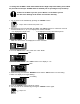
Single Unit
• The 7-Seg LED displays the 3-digit error codes one
digit at a time. The TM-RE30 (if installed) displays
the whole 3-digit error code at once.
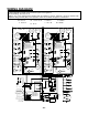
• When the right and/or left combustion section has an
error code, the red lamp next to the 7-Seg LED on the
central computer board will flash to indicate which
combustion section has the error code. Refer to the
above picture.
Example
:
If your unit has the “321” error code (inlet thermistor),
• The 7-Seg LED, will flash the 3-digit error code one
digit at a time. The 7-Seg LED will display “3”...
“2”... “1”, and then repeat the 3 digits.
• The remote controller, however, will display “321”
on its screen, in its entirety.
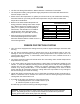
Easy Link
• The 7-Seg LED on the Master unit displays a 5-digit
number to signify which unit in the Easy Link system
has the error, and what the error code is. The 7-Seg
LED displays the number one digit at a time.
• The TM-RE30 (if installed) displays a 3-digit number
which also signifies which unit has the error, and what
the error code is.
• The unit that has the error in an Easy Link system will
display the error code on its 7-Seg LED in exactly the
same way as if it were only a Single Unit.
• When the right and/or left combustion section has an
error code, the red lamp next to the 7-Seg LED on the
central computer board will flash to indicate which
combustion section has the error code. Refer to the
above picture.
Example:
If Unit #2 has the “321” error code (inlet thermistor),
• The 7-Seg LED on the Master unit will display “3”...
“2”… “1”… “0”… “2”, displaying only one digit at a
time. The first 3 numbers indicate the error code.
The last two numbers indicate that Unit #2 has the
error.
• The remote controller, however, will display “232” on
its screen in its entirety. The first “2” indicates that
Unit #2 has the error. The “32” indicates the first two
digits of the “321” error code.
• The 7-Seg LED on Unit #2 will display “3”…. “2”…. “1”,
just like in the Single Unit example.
Error
Code
Malfunction description
Error
Code
Malfunction description
Error
Code
Malfunction description
031 Dipswitch Setting fault 391 Air-fuel Ratio Rod Failure 661
Water Control Valve Fault
(Bypass function)
101 Warning for 991 Error Code 441 Flow Sensor Failure 681 Abnormal External Fan motor
111 Ignition Failure 510 Abnormal Main Gas Valve 701 Computer board Fault
121 Flame blows out 551
Abnormal Gas Solenoid
Valve
721 False Flame Detection
311 Output Thermistor Failure 611 Fan Motor Fault 741
Miscommunication between
T-M50 and TM-RE30
321 Inlet Thermistor Failure 631 Abnormal External Pump 761
Miscommunication in Easy
link OR Multi-unit system
331 Mixing Thermistor Failure 651
Water Control Valve Fault
(Flow Adjustment function)
991 Abnormal burning
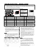
TM-RE30 (Optional)
Remote
7-Seg LED
The top red lamp will
flash when the right
combustion section has
an error code.
The mid red lamp will
flash when the left
combustion section has
an error code.