T-M32 / T-M32 ASME On-Demand Water Heater Installation Manual and Owner’s Guide For supplying potable hot water ASME model ONLY WARNING This product must be installed and serviced by a licensed plumber, a licensed gas fitter, or a professional service technician. Improper installation and/or operation, or installation by an unqualified person, will void the warranty.
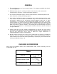
CONTENTS SPECIFICATIONS………………………. 2 INTRODUCTION………………………… 3 SAFETY GUIDELINES……………….... 4 INSTALLATION………………………….. 5 General………………………………… 6 Included Accessories….………………. 6 Outdoor Installation…………………… 7 Indoor Installation…………………...... 9 Direct Intake Vent System……………. 10 Venting Instructions………………...... 11 Gas Supply / Gas Pipe Sizing……….. 15 Water Connections…………………… 17 Pressure Relief Valve………………… 18 Electrical Connections……………...... 19 Remote Controller Connection……… 20 Pump Connection… … … … … … .
INTRODUCTION • This manual provides information necessary for the installation, operation, and maintenance of the Mobius T-M32 water heater. • The model description is listed on the rating plate which is attached to the front cover of the water heater. • Please read all installation instructions completely before installing this product. • If you have any problems or questions regarding this equipment, consult with Takagi or its local representative.
SAFETY GUIDELINES WARNING • Installation and service must be performed by a qualified installer (for example, a licensed plumber or gas fitter), otherwise the warranty by Takagi will be void. • The installer (licensed professional) is responsible for the correct installation of your Mobius T-M32 Water Heater and for compliance with all national, state/provincial, and local codes. PLEASE READ THIS MANUAL CAREFULLY AND FOLLOW ALL DIRECTIONS. GENERAL 1.
INSTALLATION All gas water heaters require careful and correct installation to ensure safe and efficient operation. This manual must be followed exactly. Read the “Safety Guidelines” section at the beginning of this manual. • The warranty will not cover damage caused by water quality. Water hardness that leads to scale formation and/or corrosion may affect/damage the water heater. Hard water scaling and/or corrosion must be avoided or controlled by proper water treatment.
GENERAL 1. The manifold gas pressure is preset at the factory. It is computer controlled and should not need adjustment. 2. Maintain proper space for servicing. Install the unit so that it can be connected or removed easily. Refer to p. 7 and p. 9 for proper clearances. 3. The electrical connection requires a means of disconnection, to terminate power to the water heater for servicing and safety purposes. 4.
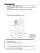
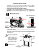
OUTDOOR INSTALLATION 1. Follow all local codes, or in the absence of local codes, follow the most recent edition of the National Fuel Gas Code: ANSI Z223.1/NFPA 54 in the USA or CAN/CSA B149.1 Natural Gas, Propane Installation Code in Canada. 2. Install outdoors only in areas with mild, temperate climates. 3. Ensure that the unit is set for outdoor installation. Locate the left bank of dipswitches to the bottom of the 7-Seg. LED on the computer board.
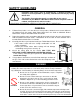
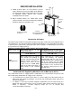
WARNING FOR INSTALLAUON LOCATIONS Do not install the heater where water, debris or flammable vapors may get into the flue terminal. This may cause damage to the heater and void the warranty. Do not have the vent terminal pointing toward any opening into a building. Do not locate your heater in a pit or location where gas and water can accumulate. Prohibited Prohibited Do not install this water heater under an overhang less than 3 feet from its top or eaves.
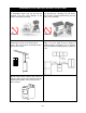
INDOOR INSTALLATION 1. Follow all local codes, or in the absence of local codes, follow the most recent edition of the National Fuel Gas Code: ANSI Z223.1/NFPA 54 in the USA or CAN/CSA B149.1 Natural Gas, Propane Installation Code in Canada. Top 12” 2. When installed indoors, the T-M32 water heater shall be located in an area to maintain the following minimum clearances around the unit: Back 1” Side 2” Side 2” Keep the following clearances.
DIRECT INTAKE VENT SYSTEM This T-M32 water heater may be converted to a direct vent (sealed combustion) appliance by installing an adapter (Part No. TM-DV32) which will bring all required combustible air from outside the building. When installing the TM-DV32 conversion kit, please follow all instructions included with the kit. • The T-M32 must be installed in a location where the proper amount of combustible air will be available to it at all times without obstructions.
VENTING INSTRUCTIONS WARNING: Improper venting of this appliance can result in excessive levels of carbon monoxide which can result in severe personal injury or death. This water heater must be vented in accordance with the section “Venting of Equipment" of the latest edition of the Natural Fuel Gas Code: ANSI Z223.1, All applicable local building codes, Section 7 of CAN/CSA B149.1 Natural Gas in Canada, Propane Installation Code in Canada.
VENT TERMINATION WARNING: Improper installation can cause nausea or asphyxiation, severe injury or death from carbon monoxide and flue gases poisoning. Improper installation will void product warranty. • The vent terminator provides a means of installing vent pipe through the building wall and must be located in accordance with ANSI Z223.1/NFPA 54, or in Canada with CAN/CSAB149.1 and local applicable codes.
Horizontal Installation Diagram Wall Vertical Condensation Drain (Install according to local codes) Sidewall Vent Terminator TK-BF01 Backflow preventor (Recommended for freezing weather conditions: 36°F and below) Rain Cap Vertical Installation Diagram Roof Roof Flashing Vertical Condensation Drain (Install according to local codes) TK-BF01 Backflow preventor (Recommended for freezing weather conditions: 36°F and below) • Regarding the clearance from the terminator to the air inlet or opening, refer
VENT CLEARANCES Canada Direct vent and other than Direct Vent U.S.A Direct vent Other than Direct Vent 1 foot A Clearance above grade, veranda, porch, deck, or balcony. 1 foot 1 foot B Clearance to window or door that may be opened. 3 feet 1 foot 4 feet from below or side opening. 1 foot from above opening.
GAS SUPPLY AND GAS PIPE SIZING TO TURN OFF GAS TO APPLIANCE 1. Turn off all electric power to the water heater if service is to be performed. 2. Turn the manual gas valve located on the outside of the unit clockwise 3 to the off position. WARNING: Conversion of this unit from natural gas to propane or vise versa cannot be done in the field. Contact your local distributor to get the correct unit for your gas type. Conversion done by anyone other than the manufacturer will void all warranty.
Size the gas pipe appropriately to supply the necessary volume of gas required for the T-M32 (240,000 BTU/H for Natural Gas or 240,000 BTU/H for Liquid Propane) using ANSI233.1/NAPA 54 in the USA or CAN/CSA B149.1 in Canada or local codes. Otherwise, flow capabilities and output temperatures will be limited. 1. Install a manual gas shut-off valve between the T-M32 and the gas supply line. 2.
WATER CONNECTIONS FOR YOUR SAFETY, READ BEFORE OPERATING: Do not use this water heater if any part has been submersed under water. Immediately call a licensed professional to inspect the water heater and to replace any damaged parts. 1. All pipes, pipe fittings, valves and other components, including soldering materials, must be suitable for potable water systems. 2. A manual shut off valve must be installed on the cold water inlet to the water heater between the main water supply line and the T-M32.
PRESSURE RELIEF VALVE The Mobius T-M32 has a high-temperature shut-off switch built in as a standard safety feature (called a Hi-Limit switch) therefore a “pressure only” relief valve is required. 1. This unit does not come with an approved pressure relief valve. 2. An approved pressure relief valve must be installed on the hot water outlet. 3. The pressure relief valve must conform to ANSI Z21.22 or CAN 1-4.4 and installation must follow local code. 4.
ELECTRICAL CONNECTIONS WARNING: Follow the electrical code requirements of the local authority having jurisdiction. In the absence of such requirements, follow the latest edition of the National Electrical Code ANSI/NFPA 70 in the U.S. or the latest edition of CSA C22.1 Canadian Electrical Code, Part 1, in Canada. CAUTION: When servicing or replacing parts within the T-M32, label all wires prior to disconnection to facilitate an easy and error free reconnection.
REMOTE CONTROLLER CONNECTION 1) Disconnect power supply from the T-M32. 2) Take off the T-M32’s front cover. 3) Please find the remote control terminal using the picture below (located around the lower right-hand side of the T-M32). 4) Open the plastic cover of the TM-RE30, and then attach the fork terminal to the connector base of the backside the TM-RE30 with two screws. Make sure the terminals are firmly fixed. 5) Put the remote wires through the hole on the bottom of the unit casing.
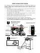
PUMP CONNNECTION The T-M32 can be used to control a recirculation pump. Proper pump control helps to preserve the life of the system and saves energy as well. The T-M32 pump control port is a “normallyopen” dry contact, and therefore needs additional components to properly control a recirculation pump. To control a recirculation pump, connect the pump to the pump connector in the T-M32 as shown in the diagram below. (In a multi-unit system, connect the pump ONLY to the “MASTER” unit.
PUMP CONTROL MODE The T-M32 provides the four types of the pump control modes. The pump control modes are selected by changing dipswitch settings. The dipswitches are located in the right bank of dipswitches in the upper-left quadrant of the computer board in the T-M32. (See the next page) A) Recirculation Control: No. 6 ON Feature: Water heaters can provide hot water as soon as possible like a recirculation usage.
D) Normal Control (Default setting): No.6 and No.7 OFF: Feature: This mode provides no special pump control. The pump operation can only be turned ON and OFF by the TM-RE30. Function: If a pump is connected to the pump control terminal and both No.6 and No.7 are OFF, the pump will be made to run all the time as long as there is a power supply to the TM32. The pump will stop when the TM-RE30 remote is turned off. Water in the loop will be maintained at set temperature.
EASY LINK SYSTEM The T-M32 can be connected with other T-M32’s with communication cables to work as a multiple manifold system. • The Easy Link system can connect up to 4 units. • A communication cable (gray color) comes with each unit. The cables use 18 gage wire and can be up to 250ft. long all together. You can manifold from 2 units to 4 units without a multi-system controller. A 4-unit system has full automatic modulation between 24,000 BTU/h and 960,000 BTU/h.
Easy Link Connection Procedures 1. Choose one of your units as the “MASTER” unit. 2. “The MASTER” Locate the left bank of dipswitches to the lower of the 7-seg. LED on the computer board of the T-M32 that you select to be the “MASTER” unit. Change dipswitch No. 8 to “ON”. Do not change any of the dipswitches on the “SLAVE” units. 3. Between the “MASTER” and the “SLAVE-1” Connect the “MASTER connector” of the “MASTER unit” to the “[1] connector” of the “SLAVE-1” unit. 4.
CAUTION SLAVE-1 unit MASTER unit D-PRT MST Left bank of Dipswitches MASTER MASTER Left bank of Dipswitches 3 4 1 2 3 4 5 6 7 8 MST Connectors ON D-PRT OUT DIRE MODE TMP3 TMP2 TMP1 3 4 1 2 3 4 5 6 7 8 OUT DIRE MODE TMP3 TMP2 TMP1 OFF ON OFF 1 2 1 2 • If you connect the “[1] (or [2]) connector” of the “MASTER” unit to the “MASTER (or [1]) connector” of the “SLAVE-1” unit, the system will not work as the easy link system. The units will work as individual units.
SLAVE-1 unit MASTER unit CAUTION 3 4 1 2 3 4 5 6 7 8 MASTER 1 2 1 2 Wrong connection between the “MASTER” unit and the “SLAVE-1” unit TMP3 TMP2 D-PRT MST MASTER MASTER MASTER Left bank of Dipswitches 3 4 1 2 3 4 5 6 7 8 OUT DIRE MODE TMP1 Left bank of Dipswitches Connectors ON OFF 3 4 1 2 3 4 5 6 7 8 D-PRT MST SLAVE-2 unit Connectors ON OFF DIRE MODE TMP3 TMP2 TMP1 Left bank of Dipswitches MASTER Communication cable OUT 3 4 1 2 3 4 5 6 7 8 D-PRT MST Left bank of Dipswitch
MULTI-UNIT SYSTEM FOR LARGE VOLUMES Multiple T-M32’s can be combined for a Multi-Unit system, along with the Multiple Unit Controller and Remote Controller (Parts TM-MC01 and TM-RE30). Each set of controllers (one TM-MC01 and one TM-RE30) can control from 2 units to 20 units for commercial or residential applications. For a 20-unit system, the computer can modulate between the usages of 24,000 BTU/h to 4.8 Million BTU/h.
In a Multi-Unit system, connect the communication cable. “[3] connector” and the “[4] connector” with the T-M32 Comunication Cables are included with the T-M32. The Cables use 18 gage wire and can be up to 250 ft. long. Wire [3] (Male Adapter) and [4] (Female Adapter) Please refer to the TM-MC01 manual for further instructions of the Multi-Unit system. 7-Seg LED Multi-unit connectors are on each unit’s computer board. Left bank of dipswitches Do not touch the Easy Link connectors.
INITIAL OPERATION FOR YOUR SAFETY, READ BEFORE OPERATING: • Check the GAS and WATER CONNECTIONS for leaks before firing it for the first time. • Open the main gas supply valve to the unit using only your hand to avoid any spark. Never use tools. If the knob will not turn by hand, do not try to force it; call a qualified service technician. Forced repair may result in a fire or explosion due to gas leaks.
NORMAL OPERATION • Flow rate to activate the T-M32: 0.5 gallon per minute • Flow rate to keep the T-M32 running : 0.4 gallon per minute 1. NORMAL OPERATION WITHOUT REMOTE CONTROLLER 1. Open a hot water tap. 3. Close the hot water tap. 2. Mix cold water with the hot to get the correct temperature water. 2. NORMAL OPERATION WITH REMOTE CONTROLLER INSTALLED: TM-RE30 (Optional) *If the TM-RE10 is used, refer to the TM-RE10 Installation Manual included with the remote. 1. Press the power ON/OFF button. 2.
*To change the TM-RE30’s mode from Default Mode to High Temperature Mode, please follow the procedures below (the TM-RE30 must be installed prior to operating these procedures): DO NOT set to 185ºF if you use your T-M32 in a recirculation system. This will cause damage to the heater and void the warranty. 1. Turn off power to the TM-RE30 by pressing the “ON/OFF" button. Lamp is OFF to indicate that power is off 2. Simultaneously press and hold both the “HOT” and “COLD” buttons for at least five seconds.
FLOW • The flow rate through the Mobius T-M32 is limited to a maximum of 9.0 GPM. • The temperature setting, along with the supply temperature of the water will determine the flow rate output of the unit. • Please refer to the temperature vs. gallons per minute chart on p.51 to determine the likely flow rates based on your local ground water temperature and your desired outlet water temperature combination.
TEMPERATURE SETTINGS • There are 8 preset temperatures that you can select from by changing the dipswitch settings on the computer board. • The temperature has been preset at the factory to 120ºF (49ºC). • If you desire to change the set temperature with dipswitches, please refer to the diagram on below. These temperatures are available: 100ºF, 115ºF, 120ºF, 135ºF, 145ºF, 155ºF, 165ºF, and 185ºF.
MAINTENANCE AND SERVICE WARNING: Turn off the electrical power supply and close the manual gas control valve and the manual water control valve before servicing. • Clean the cold-water inlet filter. (Refer to diagram below) • Be sure that all openings for combustion and ventilation air are not blocked. • Check that the exhaust vent pipe is not blocked. • Check the gas pressure. • Keep the area around the water heater clear. Remove any combustible materials, gasoline or any flammable vapors and liquids.
GENERAL TROUBLESHOOTING ~ TEMPERATURE and AMOUNT OF HOT WATER ~ PROBLEM POSSIBLE SOLUTIONS It takes long time to get hot water at the fixtures. • The time it takes to deliver hot water from the TM32 to your fixtures depends on the length of piping between the two. The longer the distance or the bigger the pipes, the longer it will take to get hot water. • If you would like to receive hot water to your fixtures quicker, you may want to consider a hot water recirculation system. (p.
~ WATER HEATER ~ PROBLEM POSSIBLE SOLUTIONS Unit does not ignite when water goes through the unit. • • • • The fan motor is still spinning after operation has stopped. • This is normal. After operation has stopped, the fan motor keeps running for 35 seconds in order to reignite quickly, as well as push all exhaust gas out of the flue. Abnormal sounds come from the unit. • Contact TAKAGI. Is the flow rate over 0.5 GPM? (p. 31) Check for the filter on cold water inlet. (p.
TROUBLESHOOTING – ERROR CODES • • All Takagi units are self diagnostic for safety and convenience when trouble shooting. If there is a problem with the installation or the unit, it will display a numerical error code on the TM-RE30 (if installed) or on the 7-Seg LED of the central computer board and section computer board to communicate the source of the problem. • Consult the following chart for the cause of each error code.
WIRING DIAGRAM A wiring diagram is located on the inside front panel of the appliance. Electrical Rating: 120 VAC, 60 Hz. Note: If any of the original wiring supplied with this appliance must be replaced, it must be replaced with appliance wiring material (180c) or its equivalent. Wires are available through the manufacturer.
OPERATING SAFETY FOR YOUR SAFETY READ BEFORE OPERATING WARNING: If you do not follow these instructions exactly, a fire or explosion may result causing property damage, personal injury or loss of life. A. This water heater does not have a pilot. It is equipped with an ignition device that automatically lights the burner. Do not try to light the burner by hand. B. BEFORE OPERATING smell all around the water heater area for evidence of leaking gas.
DANGER Vapors from flammable liquids will explode and catch fire causing death or severe burns. Do not use or store flammable products such as gasoline, solvents or adhesives in the same room or area near the water heater. Keep flammable products: 1. Far away from heater. 2. In approved containers. 3. Tightly closed 4. Out of children's reach Vapors: 1. Cannot be seen 2. Vapors are heavier than air 3. Go a long way on the floor 4.
APPLICATIONS Space Heating Applications WARNING • Toxic chemicals used in boiler treatments such as alcohol, glycerol and glycol group must not be introduced into the system when used for open loop potable water and space heating. • The T-M32 can be used to supply potable water and space heating and shall not be connected to any heating system or component(s) previously used with non-potable water where any chemicals were added to the water heating appliances.
Dual-purpose hot water heating (Domestic and Space Heating): Diagramatic Layout of Radiant Heating and Domestic Water Heater Per Mass. Code An approved Pressure Only Relief Valve, Tie to Location approved by Local Codes and Must Meet BTU Rating of Takagi Model Used Cold Inlet Apply Correct Thermal Expansion Tank-Size Per Application Shut-Off Valve 4" Gas Exhaust Vent (Discharge Must Comply with Local and State Codes).
ADDITIONAL CLEARANCES Please follow all local and national codes in regards to proper termination clearances. In the absence of such codes, the following clearances can be used as guidelines. Local codes supersede these guidelines. For sidewall terminations 2ft. 1ft. 3ft. 2ft. 1ft. 1ft. 3ft. 1ft. 3ft. Inside corner Inside corner Air supply inlet Direct vent termination Exhaust termination For multiple sidewall exhaust terminations (e.g.
OPTIONAL ITEMS 1. TM-RE30 Temperature Remote Controller The TM-RE30 Temperature Remote Controller has two functions. It allows the output temperature from the TM32 to be adjusted within the range of 100 °F to 185 °F, and it also works as a diagnostic tool that will give a concise error code whenever there is a problem with the unit. The temperature options are 100°F, 105°F, 110°F, 115°F, 120°F, 125°F, 130°F, 135°F, 140°F, 145°F, 150°F, 155°F, 160°F, 165°F, 170°F, 175°F, 180°F and 185°F.
COMPONENTS DIAGRAM 052 Case assembly Other than the front cover (No.9), all of the T-M32 ASME’s parts are the same as the T-M32. ASM 702 051 051 004 052 003 050 001 005 E 010 011 007 051 052 007 004 052 006 009 T-M32 ASME 050 002 008 052 703 052 Computer board assembly Other than Part# 706, the T-M32 and the T-M32 ASME share the same components.
Burner assembly The T-M32 and the T-M32 ASME share the same components.
Other than Part# 211, Part# 439, Part# 440 and Part# 441, the T-M32 and the T-M32 ASME share the same components.
PARTS LIST Other than the front cover (No.9), burner assembly (No.211), hot pipe (No.439), cold pipe (No.440), connection pipe (No.441) and “flow sensor, gas proportional valve connection and thermistors” wire (No.706), all of the T-M32 ASME’s components are the same as the T-M32.
Item# Part# Description Item# Part# Description 410 EX002 Heater 101 437 EZM18 O-ring P18 FKM 411 EM404 Water inlet 439 EM45E Hot pipe for T-M32 ASME 412 EZN16 O-ring JASO# 1016 FKM 440 EM45D Cold pipe for T-M32 ASME 413 EX021 Heater plate 441 EM45F Connection pipe for T-M32 ASME 414 415 EX01H EKK2P Fastener “16AG” Inlet heater 701 702 EM376 EM454 T-M32 PCB Transformer 416 EK239 Outlet drain plug 703 EM463 Junction box inner plate 417 EZM06 O-ring P6 FKM 704 EM3
OUTPUT TEMPERATURE CHART Out Put Tem perature vs. GPM (Max. 9.0 GPM) w ith Various Ground Water Tem perature Correct Gas pipe size can be expect this chart 10.0 Out Put Hot Water GPM 9.0 8.0 7.0 6.0 5.0 4.0 3.0 2.0 1.0 0.0 100 105 110 115 120 125 130 135 140 150 160 165 170 175 180 185 40 F 6.4 5.9 5.5 5.1 4.8 4.5 4.3 4.0 3.8 3.5 3.2 3.1 2.9 2.8 2.7 2.6 50 F 7.7 7.0 6.4 5.9 5.5 5.1 4.8 4.5 4.3 3.8 3.5 3.3 3.2 3.1 2.9 2.8 60 F 9.0 8.5 7.7 7.0 6.4 5.
3. Warranty for models: T-M32, T-M32 ASME [Unit: Year] (1) Parts Labor Application HX No Recirculation 10 (2) On-Demand Recirculation 5 Single Family Aquastat Control (3) Domestic Hot 1 5 w/ Standard Takagi Pump Control Water Recirculation Timer Only 3 3 No Pump Control (24 hr.) No Recirculation Commercial (2) On-Demand Recirculation 5 5 or Aquastat Control (3) Multi-Family 1 w/ Standard Takagi Pump Control Domestic Hot Recirculation Timer Only Water 3 3 No Pump Control (24 hr.