
Installation Guide/Owner's Manual

- 25 -
M
A
S
T
E
R
S
L
A
V
E
O
U
T
M
S
T
OFF
ON
D
I
R
E
O
U
T
T
M
P
3
T
M
P
2
T
M
P
1
1
2
3
4
5
6
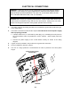
Communication cable
S
L
A
V
E
I
N
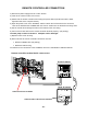
Connectors
Dipswitch
M
A
S
T
E
R
S
L
A
V
E
O
U
T
M
S
T
OFF
ON
D
I
R
E
O
U
T
T
M
P
3
T
M
P
2
T
M
P
1
1
2
3
4
5
6
S
L
A
V
E
I
N
Connectors
Dipswitch
M
A
S
T
E
R
S
L
A
V
E
O
U
T
M
S
T
OFF
ON
D
I
R
E
O
U
T
T
M
P
3
T
M
P
2
T
M
P
1
1
2
3
4
5
6
Communication cable
S
L
A
V
E
I
N
Connectors
Dipswitch
M
A
S
T
E
R
S
L
A
V
E
O
U
T
M
S
T
OFF
ON
D
I
R
E
O
U
T
T
M
P
3
T
M
P
2
T
M
P
1
1
2
3
4
5
6
S
L
A
V
E
I
N
Connectors
Dipswitch
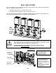
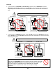
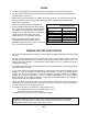
CAUTION
• If you connect the “SLAVE IN (or SLAVE OUT) connector” of the “MASTER” unit to the
“MASTER (or SLAVE IN) connector” of the “SLAVE-1” unit, the system will not work as a
easy link system. The “ON LINE” lamps will stay unlit and the units will work as individual
units.
OR
• If you connect the “MASTER connector” of the “SLAVE-1” unit to the “SLAVE IN connector”
of the “SLAVE-2” unit, the “SLAVE-2” unit will work as an individual unit, and will not be part
of the easy link system.
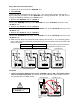
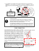
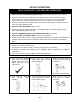
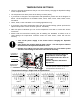
WARNING
Connecting two “MASTER connectors” together from two separate units may
damage the computer board. The communication cable has a female end
and a male end so it’s impossible to have a MASTER -to- MASTER
connection with the communication cable. Do not splice or modify
connectors.
MASTE
R
unit SLAVE-1 unit
Wrong connection between the “MASTER” unit and the “SLAVE-1” unit
MASTE
R
unit
SLAVE-1 unit
MASTE
R
unit
SLAVE-1 unit
SLAVE-2 unit
Wrong connection between the “SLAVE-1” unit and the “SLAVE-2” unit
M
A
S
T
E
R
S
L
A
V
E
O
U
T
M
S
T
OFF
ON
D
I
R
E
O
U
T
T
M
P
3
T
M
P
2
T
M
P
1
1
2
3
4
5
6
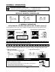
Communication cable
S
L
A
V
E
I
N
Connectors
Dipswitch
M
A
S
T
E
R
S
L
A
V
E
O
U
T
M
S
T
OFF
ON
D
I
R
E
O
U
T
T
M
P
3
T
M
P
2
T
M
P
1
1
2
3
4
5
6
S
L
A
V
E
I
N
Connectors
Dipswitch
M
A
S
T
E
R
S
L
A
V
E
O
U
T
M
S
T
OFF
ON
D
I
R
E
O
U
T
T
M
P
3
T
M
P
2
T
M
P
1
1
2
3
4
5
6
S
L
A
V
E
I
N
Connectors
Dipswitch
Prohibited