
Manual

- 27 -
Propor-
tional
Valve
3
9
5
3
7
3
G
W
BK
Trans-
former
IG
Elect rod
Heater
Thermostat
Heater
Ground
BK
BK
MV
SV3
SV2
SV1
LB
G
O
R
O.H.C.F
Hi-
limit
BL
BLBL
BL
BL
BL
BL
W
Y
B
L
O
R
FM
W
R
Flow
Sensor
Flame rod
Ground
Air-fuel ratio rod
Y
G
O
Inlet
thermistor
Outlet
thermistor
Remote
Controller
65432
1
BK
Flow
Adjust
Valve
R
BK
OFF
P
P
P
P
BR
BR
AC120V
G
Ground
BK
W
W
BK
BR
BR
SW
Fuse
box
W
BK
BK
Increase button
Decrease button
Dip switch
Burning lamp
MAX button
MIN button
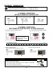
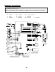
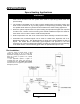
WIRING DIAGRAM
A wiring diagram is located on the inside front panel of the appliance.
Electrical Rating: 120 VAC, 60 Hz
Note: If any of the original wiring supplied with this appliance must be replaced, it must be replaced with
appliance wiring material (180c) or its equivalent. Replacement wires are available through Takagi.
W: WHITE
R: RED
BK: BLACK
P: PURPLE
LB: LIGHT BLUE
BL: BLUE
G: GREEN
Y: YELLOW
O: ORANGE BR: BROWN