
Installation Guide/Owner's Manual


- 35 -
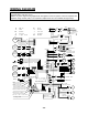
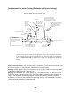
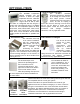
WIRING DIAGRAM
A wiring diagram is located on the inside front panel of the appliance.
Electrical Rating: 120 VAC, 60 Hz
Note: If any of the original wiring supplied with this appliance must be replaced, it must be replaced with
appliance wiring material (180c) or its equivalent. Replacement wires are available through Takagi.
Propor-
tional
Valve
3
9
53
73
GFI
G
BK
W
AC120V
Trans-
former
3A
G
Ground
IG
Elect rod
Heater
Freeze
protection
thermostat
Heater
Ground
BK
BK
MV
SV3
SV2
SV1
LB
G
O
R
O.H.C.F
Hi-
limit
switch
BL
BL BL
BL
BL
BL
BL
W
Y
B
L
O
R
F
M
W White
R Red
BK Black
P Purple
LB Light blue
BL Blue
G Green
Y Yellow
O Orange
BR Brown
SLAVE IN
B
K
W
R
B
K
W
R
W
R
R
Flow
Sensor
W
Bypass
Valve
Flame rod
Ground
AFR rod
Y
G
O
Inlet
thermistor
Output
thermistor
Mixing
thermistor
Remote
Controller
Pump
MASTER
SLAVE OUT
BK
W
BK
W
65432
1
BK
BK
BK
BK
BK
BK
BK
BK
W
Flow
Adjust
ment
Valve
R
R
R
R
B
K
B
K
B
K
B
K
Multi-system
On line lamp
7 Seg LED
33
7
7
OFF
1
23456
OFF
P
P
P
P
B
R
B
R
B
R
B
R
MAX button
MIN button
Increase button
Decrease button
Burning lamp
Dip switch
Error call button
B
K
B
K
W
W