
Service Handbook


64 • Condensing Models: On-Demand Water Heater Service Handbook
MAINTENANCE
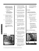
Secure these wires with the
cable clamp on the le side
of the cabinet.
12.1
Install the fuse box assembly
on the le side of the manifold
plate. (See items 703 & 120,
page 68.) Hand ghten
two screws to secure it to the
manifold plate.
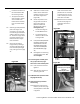
13. In stall the computer board (PCB):
•
Small feet at the bottom must fit
into the corresponding holes in
the case.
•
Insert the screw at the top of the
computer board, then hand-
tighten it to secure the board to
the fuse box assembly. See item
701, page 68.
13.1 Connect all of the wires to
the computer board. All
of the wire connectors are
uniquely sized and shaped
to fi t only in the correct
connector on the board.
Refer to the schematic on
page 22.
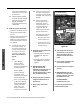
NOTE:
•
Indoor Models:
There are two (2)
receptacles on the
computer board that will
be open (Figure 83).
Outdoor Models:
There are three (3)
receptacles on the
computer board that will
be open (Figure 83).
•
Item “I” in the schematic
(p. 22) uses a separate
wiring assembly which
includes three wires:
yellow, green, and
orange.) Install it as
shown in the schematic.
13.2
Insert the connector from
the power supply cable to
the top port on the fuse box.
If needed, refer to Figure 75,
page 60.
13.3
Use screws to secure
three (3) green wires to
the bo om, center of
the manifold plate. See
“Ground Connec ons”
in Figure 24, page 35.
(There are two moun ng
holes for these wires.)
The three green wires can
be iden fi ed as follows:
•
One green wire comes
from the power cord.
•
Two green wires come
from connectors on the
computer board.
14. Complete the wiring connec ons
inside the cabinet:
•
Locate the plug and receptacle
with blue wires. Plug them
together.
•
Locate the plug and receptacle
with yellow wires. Plug them
together.
15. INDOOR MODELS ONLY:
Plug the wires from the
temperature controller (item 721,
p. 67) to the matching wires
from the computer board. (These
wires are black and white).
16. Verify that all water connec ons
are ght and that there are no
parts le over.
17. Re sto re p ower to the water
heater.
18. Open the gas valve slowly and
check for leaks. If any gas leaks
appear, shut off the gas and
disconnect power to the water
heater.
19. Turn on water to the heater and
test for proper opera on.
20. Verify that there are no water or
gas leaks.
21. INDOOR MODELS: Insert the
temperature controller into the
opening of the front cover, then
reinstall the front cover.
OUTDOOR MODELS:
Reinstall the front cover.
If you have any questions, please
contact technical support.
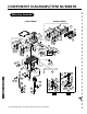
Figure 83.
TWO OPEN
(ALL MODELS)
OPEN
(OUTDOOR MODELS)
OPEN CONNECTORS ON THE COMPUTER BOARD:
• TWO FOR INDOOR MODELS
• THREE FOR OUTDOOR MODELS