
Service Handbook


Condensing Models: On-Demand Water Heater Service Handbook • 55
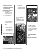
MAINTENANCE
Flow Sensor/
Control Valve
Removal and
Installa on
Tools:
#2 Phillips Screw Driver
See also Checking the Flow Sensor,
page 27.
Removal
1. Shut off power by disconnec ng
the power cord or shu ng off the
power disconnect.
2. Shut off the gas supply to the
water heater.
3. Drain the water from the water
heater.
3.1 Close the shutoff valves on
the hot and cold side of the
heater.
3.2
If isola on valves are
installed, open the drain
ports.
3.3
If isola on valves are not
installed, remove the fi lter
(item 405, p. 70) and open
the pressure relief valve.
4. FOR INDOOR MODEL ONLY:
Remove the Temperature
Controller (item 721, p. 67)
by disconnec ng it at the
white connectors that go to the
computer board.
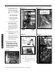
5. Remove the computer board
(PCB). See Item 701, p. 68; see
also Figure 41.
5.1 Disconnect all wires from
the PCB.
5.2
Remove the screw at the top
and remove the board.
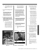
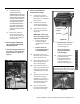
6. Remove the fl ow sensor/control
valve (item 402, p. 70) as follows:
6.1 Remove fasteners 16A and
14-22 (items 458, 459)
6.2
Pull the cold connec on
tube (item 462, p. 70)
from the outlet of the fl ow
sensor/control valve, then
li the valve off the inlet
connec on. You may have
to twist the valve off inlet
connec on.
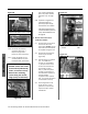
7. Inspect the o-rings on the inlet
water connec on and the cold
connec on tube for cuts or wear.
Replace as needed.
•
O-ring on inlet water connection:
part no. 319143-083.
•
O-ring on cold connection tube:
part no. 319143-100.
Installa on
1. Install the fl ow sensor/control
valve (item 402, p. 70) onto the
inlet water connec on.
2. Connect the cold water connection
tube (item 462, page 70) to the
outlet of the flow sensor/control
valve.
3. Install the fasteners:
•
One 16A fastener. See item
459 on p. 70, which secures
the inlet of the flow sensor/
control valve to the inlet water
connection. “16A” is marked on
the end of this clip.
•
Two 14-22 fasteners. (“14-22” is
marked on the end of each clip.)
See both instances of item 458
on page 70. These fasteners
secure the cold connection tube
at each end. Install as described
in Figure 60, page 52.
See also connection points “B”
and “D” on page 70. The cold
connection tube’s brass rings
must be fully inserted at each
connection point.
4. Turn on the water and verify
that there are no leaks at the
connec ons. If there are leaks,
shut off the water, drain the water
heater, and fi x the leak.
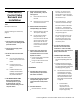
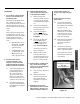
5. Install the computer board (PCB):
•
Small feet at the bottom must fit
into the corresponding holes in the
case.
•
Insert the screw at the top of the
computer board, then hand-tighten
it to secure the board to the fuse box
assembly. (Figure 62, page 52.)
5.1 Connect all of the wires to the
computer board. All of the
wire connectors are uniquely
sized and shaped to fi t only in
the correct connector on the
board. Refer to the schema c
on page 22.
•
Indoor Models:
There are two (2)
receptacles on the
computer board that will
be open (Figure 65).