
Service Handbook


Condensing Models: On-Demand Water Heater Service Handbook • 39
MAINTENANCE
part number 319143-044 (item
113) and/or 319143-045 (item
114). See page 69.
9.12
Inspect the o-ring (item 151,
p. 69) and gas inlet ring
(item 119, p. 69) on the
gas connec on for cuts or
breaks.
If damaged, replace with
part number 319143-057
(item 151) and/or 319143-
049 (item 119). See page
69.
10. Disconnect and remove the fan
from the combus on chamber as
follows:
10.1 Remove the clear air tube
from the bo om of the
combus on chamber. If
needed, refer to Figure 33,
page 41.
10.1 Remove the 2 Phillips/hex
head screws poin ng down
from the fan using an 8”
long, #2 Phillips head screw
driver. There are 2 holes
in the case directly below
the screws to put the screw
driver through.
10.2
Slide the fan toward you
to remove it from the rear
slots that hold it in place.
Remove the fan.
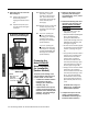
11. Rem ove the burner from the
combus on chamber:
11.1
Remove two screws below the
burner, at the back (Figure 29).
11.2
Remove three screws across
the front of the burner. See
Figure 29. Do not remove
the screws around the fl ame
sensor/AFR and igniter rods.
11.3
Slide the burner out toward
you. You may need to use a
small set of pliers to loosen
the burner on the sides and
then pull from the middle
por on of the inlet holes.
11.4
Check the gaskets on the
burner for any tears. If
there are, replace the gasket
with part number 319143-
032.
12. Disconnect and remove the
following items:
12.1
Disconnect the condensate
drain line (item 415, page
70) from the secondary
heat exchanger assembly
by pulling down. Do not
remove the drain line from
the outlet connec on at the
bo om of the cabinet.
12.2
Remove fastener 16-25
(item 460, page 70) from
the outlet tubing and outlet
water connec on.
12.3
Slide the outlet tube up
and out of the outlet water
connec on. Remove the tube.
12.4
Disconnect the ven ng from
the exhaust fl ue.
12.5
Remove the three screws
at the top of the secondary
heat exchanger that are
securing it to the case. Refer
to Figure 30.
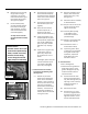
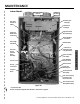
Example:
Freeze Protection Heaters
with Clips
Figure 28.
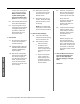
Front View of Burner Assembly
Three ScrewsThree Screws
Two Screws
Area Beneath Burner (Inside Cavity)
Figure 29.
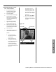
Figure 30.
Three Screws Securing the
Secondary Heat Exchanger