
Installation Sheet

7 Page
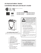
INSTALLATION
GENERAL
1. Follow all local codes, or in the absence of local codes, follow the most recent edition of the National
Fuel Gas Code: ANSI Z223.1/NFPA 54 in the USA or CAN/CSA B149.1 Natural Gas, Propane Installation
Code in Canada.
2. All gas water heaters require careful and correct installation to ensure safe and efficient operation. This
manualmustbefollowedexactly.Readthe“SafetyGuidelines”section.
3. The manifold gas pressure is preset at the factory. It is computer controlled and should not need
adjustment.
4. Maintain proper space for servicing. Install the unit so that it can be connected or removed easily.
Refertothe"Clearances"sectiononp.9forproperclearances.
5. The water heater must be installed in a location where the proper amount of combustible air will be
available to it at all times without obstructions.
6. The electrical connection requires a means of disconnection, to terminate power to the water heater
for servicing and safety purposes.
7. Do not install the unit where the exhaust vent is pointing into any opening in a building or where the
noise may disturb your neighbors. Make sure the vent termination meets the required distance by
local code from any doorway or opening to prevent exhaust from entering a building (refer to p. 18).
8. Particles from flour, aerosols, and other contaminants may clog the air vent or reduce the functions
oftherotatingfanandcauseimproperburningofthegas.Regularlyensurethattheareaaroundthe
unit is dust- or debris-free; regular maintenance is recommended for these types of environment.
9. If you will be installing the water heater in a contaminated area with a high level of dust, sand, flour,
aerosols or other contaminants/chemicals, they can become airborne and enter and build up within
the fan and burner causing damage to the water heater.
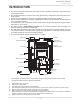
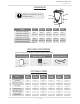
10.Forthe240Indoor(T-H3J-DV),340Indoor(T-H3S-DV)and540Indoor(T-H3-DV)models:
are installed indoors only and equipped with a thermistor and hi-limit switch for the exhasut gas,
detecting excess temperatures within the flue and enabling the unit to safely stop operations if
needed. These components are always monitoring exhaust gas conditions in order to prevent heat
damagetoPVC(Plastic)ventingifPVCisused.
If the exhaust gas temperature exceeds 140°F, these components will enable the unit to safely stop
operations. (For the Outdoor model, these components are not available since there’s no exhaust
venting required.)
•TheDirectVentIndoormodelrequiresa3"or4”make-upintakeairsupplypipe.Theintakepipe
must be sealed airtight.
•AirsupplypipecanbemadeofABS,PVC,corrugatedstainlesssteel,orCategorylll/IVstainlesssteel.
•SidewallventingisrecommendedfortheDirectVentIndoormodel.Verticalventing(roof
termination) is acceptable.
•The manufacturer recommends running the exhaust vent and the intake pipe as parallel as possible.
11. For the 240 Outdoor (T-H3J-OS), 340 Outdoor (T-H3S-OS) and 540 Outdoor (T-H3-OS) models:
•To be installed outdoors and only in areas with mild, temperate climates.
•The Outdoor model shall be wall-mounted or mounted on a stand. Locate the Outdoor model in
an open, unroofed area and maintain the following minimum clearances:
Thereisa2”clearancefromtheleftandrightsidesoftheunittocombustibleandnon-
combustible surfaces.
However, if any portion or area of the surface is exposed to the exhaust fumes (i.e. directly to
thesidesoftheventcap),thatsurfacemustbeatleast24”away
.
Installaon
Installaon Manual