On-Demand Water Heater Installation Manual and Owner’s Guide ANSI Z21.10.3 and CSA 4.3 Models 540 (T-H3) models only • 240 Indoor (T-H3J-DV) • 340 Indoor (T-H3S-DV) • 540 Indoor (T-H3-DV) • 240 Outdoor (T-H3J-OS) • 340 Outdoor (T-H3S-OS) • 540 Outdoor (T-H3-OS) If the information in these instructions is not followed exactly, a fire or explosion may result causing property damage, WARNING personal injury or death.
CONTENTS Installation Manual SPECIFICATIONS........................................................................................................................... 4 INTRODUCTION........................................................................................................................... 5 SAFETY GUIDELINES..................................................................................................................... 6 INSTALLATION........................................................
Installation Manual Contents Installation Manual CONGRATULATIONS Congratulations and thank you for choosing our tankless water heater. Before use, we recommend that you read through this safety manual carefully. Please refer to the back of the manual for details about the warranty. Keep this manual for future reference. If you lose the manual, contact the manufacturer or your local distributor.
Installation Manual Specifications SPECIFICATIONS 240 Indoor Model 240 Outdoor 340 Indoor 340 Outdoor 540 Indoor 540 Outdoor (T-H3J-DV) (T-H3J-OS) (T-H3S-DV) (T-H3S-OS) (T-H3-DV) (T-H3-OS) Natural Gas Input (Operating Range) BTU/h Min.: 15,000 Max.: 160,000 Min.: 15,000 Max.: 180,000 Min.: 15,000 Max.: 199,000 Propane Input (Operating Range) BTU/h Min.: 13,000 Max.: 160,000 Min.: 13,000 Max.: 180,000 Min.: 13,000 Max.
Installation Manual Introduction INTRODUCTION • This manual provides information necessary for the installation, operation, and maintenance of the water heater. • The model description is listed on the rating plate which is attached to the side panel of the water heater. • Please read all installation instructions completely before installing this product. • If you have any problems or questions regarding this equipment, consult with the manufacturer or its local representative.
Installation Manual Safety Guidelines SAFETY GUIDELINES SAFETY DEFINITION DANGER WARNING CAUTION Indicates an imminently hazardous situation which, if not avoided, will result in death or serious injury. Indicates an imminently hazardous situation which, if not avoided, could result in death or serious injury. Indicates an imminently hazardous situation which, if not avoided, could result in minor or moderate injury. GENERAL 1.
Installation Manual Installation INSTALLATION GENERAL 1. Follow all local codes, or in the absence of local codes, follow the most recent edition of the National Fuel Gas Code: ANSI Z223.1/NFPA 54 in the USA or CAN/CSA B149.1 Natural Gas, Propane Installation Code in Canada. 2. All gas water heaters require careful and correct installation to ensure safe and efficient operation. This manual must be followed exactly. Read the “Safety Guidelines” section. 3.
Installation Manual Installation • Installation and service must be performed by a qualified installer (for example, a licensed plumber or gas fitter), otherwise the warranty will be void. WARNING • The installer (licensed professional) is responsible for the correct installation of the water heater and for compliance with all national, state/provincial, and local codes. • The manufacturer does not recommend installing the water heater in a pit or location where gas and water can accumulate.
Installation Manual Installation CLEARANCES Top Maintain all clearances around the water heater. Black Side Front Side Bottom Model Top Bottom Front Back Sides 240 Indoor (T-H3J-DV) 340 Indoor (T-H3S-DV) 540 Indoor (T-H3-DV) 12 in. (305 mm) 12 in. (305 mm) 4 in.* (102 mm) 0.5 in. (13 mm) 2 in. (51 mm) 240 Outdoor (T-H3J-OS) 340 Outdoor (T-H3S-OS) 540 Outdoor (T-H3-OS) 36 in. (914 mm) 12 in. (305 mm) 24 in. (610 mm) 0.5 in. (13 mm) 2 in. (51 mm) *24 inch recommended for maintenance.
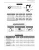
Installation Manual Installation 1. Temperature remote controller: 9008172005 (TM-RE40) 2. Backflow Preventer: 9007678005 (TK-BF01) The Temperature Remote Controller has two functions. It allows the output temperature from the water heater to be adjusted within the range of 100 °F to 185 °F, and it also works as a diagnostic tool that will give a concise error code whenever there is a problem with the unit.
WARNING FOR INSTALLATIONS FOR YOUR SAFETY, READ BEFORE INSTALLATION: Do not install the heater where water, debris or flammable vapors may get into the flue terminal. This may cause damage to the heater and void the warranty. Prohibited Do not have the vent terminal pointing toward any opening into a building. Do not locate your heater in a pit or location where gas and water can accumulate. Prohibited Do not install this water heater under an overhang less than 3 ft. (914 mm) from its top or eaves.
Installation Manual Installation HIGH-ALTITUDE INSTALLATIONS Check the elevation where your water heater is installed. Set DIPswitches shown in the table below depending on the altitude.
Installation Manual Installation VENTING INSTRUCTIONS For the 240 Indoor (T-H3J-DV), 340 Indoor (T-H3S-DV) and 540 Indoor (T-H3-DV) models -General• Improper venting of this appliance can result in excessive levels of carbon monoxide which can result in severe personal injury or death. • Improper installation can cause nausea or asphyxiation, severe injury or death from carbon monoxide and flue gases poisoning. Improper installation will void DANGER product warranty.
-DIPswitch settings for Vent lengthSet DIPswitches shown in the table below depending on the vent length. 240 Indoor (T-H3J-DV) 340 Indoor (T-H3S-DV) 3" ventings 540 Indoor (T-H3-DV) (Upper bank of DIPswitches) ON 1 2 3 4 5 6 7 8 9 10 ON 1 2 3 4 5 6 7 8 OFF OFF No. 6 : ON No. 7 : OFF No. 3 : ON No. 4 : OFF ON 1 2 3 4 5 6 7 8 9 10 ON 1 2 3 4 5 6 7 8 OFF OFF No. 6 : OFF No. 7 : OFF No. 3 : OFF No. 4 : OFF ON 1 2 3 4 5 6 7 8 9 10 ON 1 2 3 4 5 6 7 8 OFF OFF No. 6 : ON No. 7 : ON No.
Installation Manual Installation • The maximum length of exhaust vent piping must not exceed 70 ft. (21.3 m) for 3” venting, which depends on elevation where the water heater installaed. See the table below and 100 ft. (30.5 m) for 4” venting (deducting 5 ft. (1.5 m) for each elbow used in the venting system). Do not use more than 5 elbows. • When the horizontal vent run exceeds 5 ft. (1.5 m), support the vent run at 3 ft. (0.9 m) intervals with overhead hangers. Diameter Max. No. of Elbow Max.
Installation Manual Installation 3" vent connection Diagram (For 3" only) 1. Connect the 3" PVC socket directly on the exhaust/Intake vent collar of the water heater. 2. Connect a 3” PVC straight pipe to the PVC socket.
Diameter Max. No. of Elbow Max. Vertical and Horizontal (Total) Vent Length 4 in. (102 mm) 5 100 ft. (30.5 m ) *For each elbow added, deduct 5 ft. (1.5 m) from max. vent length. No. of Elbows 0 1 2 5 Max. Vertical or Horizontal Vent Length 100 ft. (30.5 m) 95 ft. (29.0 m) 90 ft. (27.4 m) 75 ft. (22.9 m) Excludes elbow termination, rain caps, or the 4 in.
Installation Manual Installation -Vent termination clearancesINSIDE CORNER DETAIL V Vent terminal X Air supply inlet V Area where is not permitted G H A D E V B B B C V F V FIXED ED CLOS E BL A OPER V L V ED ABLE FIXLOSED C OPER V B B V I X M V X K J A Gas meter / regulator B A Canada Direct vent and other than Direct Vent Direct vent 1 foot 1 foot 1 foot 3 feet 1 foot 4 feet from below or side opening. 1 foot from above opening.
Installation Manual Installation -For sidewall terminations2 ft. 1 ft. (610 mm) (305 mm) 1 ft. (305 mm) Exhaust termination Inside corner 2 ft. (610 mm) 1 ft. (305 mm) 1 ft. (305 mm) Combined intake and exhaust termination Inside corner Exhaust termination 3 ft. (915 mm) 3 ft. (915 mm) 3 ft. (915 mm) For multiple sidewall exhaust terminations (e.g. multiunit systems), an exhaust termination must be at least 1 ft. (305mm) away from another exhaust termination.
Installation Manual Installation GAS SUPPLY AND GAS PIPE SIZING -General- CAUTION • Check that the type of gas matches the rating plate first. • Ensure that any and all gas regulators used are operating properly and providing gas pressures within the specified range shown below. Excess gas inlet pressure may cause serious accidents. • Conversion of this unit from natural gas to propane or vise versa will void all warranty. Contact your local distributor to get the correct unit for your gas type.
Installation Manual Installation -Natural Gas Supply PipingMaximum delivery Capacity of Cubic Feet of Gas per Hour of IPS Pipe carrying Natural Gas with 0.60 Specific Gravity Based on Pressure Drop of 0.5" W.C. Based on Energy Content of 1,000 BTU/Cubic ft.: The water heater requires 160 Cubic ft./hr for the 240 (T-H3J) models, 180 Cubic ft./hr for the 340 (T-H3S) models, and 199 Cubic ft./hr for the 540 (T-H3) models.
Installation Manual Installation -Measuring inlet gas pressure1. Turn off all electric power to the water heater if service is to be performed. 2. Turn the manual gas valve located on the outside of the unit clockwise to the off position. The water heater cannot perform properly without sufficient inlet gas pressure. Below are instructions on how to check the inlet gas pressure. THIS IS ONLY TO BE DONE BY A LICENSED PROFESSIONAL. 1. Shut off the manual gas valve on the supply gas line. 2.
Installation Manual Installation -Pressure relief valveThe water heater has a high-temperature shut off switch built in as a standard safety feature (called a Hi-Limit switch) therefore a “pressure only” relief valve is required. • This unit does not come with an approved pressure relief valve. • An approved pressure relief valve must be installed on the hot water outlet. • The pressure relief valve must conform to ANSI Z21.22 or CAN 1-4.4 and installation must follow local code.
-Condensate Drain Connections- WARNING Discharge condensate (acidic water) in accordance with all local codes and common safety practices. The water heater is high efficiency condensing water heater that produces condensate (acidic water). The acidic condensate generated in the secondary heat exchanger can be neutralized by the Neutralizer accessory. Case A: If a neutralizer is not required 1. Connect a 1/2” FPT X 3/8” (or 1/2”) HB Adaptor to the condensate drain port at the bottom of the water heater.
• The condensate drain is at atmospheric pressure (non-pressurized) and therefore must be allowed to drain freely with gravity only. Please ensure that there are no blockages along the condensate drain tube. All portions of the condensate drain (neutralizer and drain tube) must be at a lower elevation WARNING than the water heater to prevent condensate water from building up inside the heat exchanger.
Installation Manual Installation TEMPERATURE REMOTE CONTROLLER -INCLUDED ACCESSORIES (Outdoor models only)Check that these items below are included with the remote controller. Temperature Remote Controller Screws Qty: 1 Manual Qty: 2 Qty: 1 Remote controller cable Qty: 1 -INSTALLATION- CAUTION • This remote controller is NOT waterproof Do not install in high temperature environments, steamy conditions (such as a bath room), outdoors, in direct sunlight, or within the reach of children.
3. Tighten the two "Fork terminals" beneath the two "Remote controller terminal" screws on the back of the main body. (Fig. C-1) 4. Cut out the inlet for the remote controller cable from the bottom of the main body. (Fig. C-2) 5. Place the “Main body” back on the "Back plate", with the "Remote controller cable" running out of the bottom inlet. Fig. C-1 Remote controller terminals Fig.
240 (T-H3J) and 340 (T-H3S) models 9008172005 (TM-RE40) Connect other end to these terminals 540 (T-H3) models 9008172005 (TM-RE40) Connect other end to these terminals 28 Page
Installation Manual Installation EASY-LINK SYSTEM (Available on the 540 (T-H3) models only) -GeneralThe 540 (T-H3) models water heaters can be connected with allowable heaters (see the table below) with communication cables to work as a multiple-unit manifold system. • The Easy-Link system allows up to 4 units to manifold together. • A communication cable (gray color) comes with each 540 (T-H3) models. You can manifold from 2 to 4 units without the need for a multi-unit controller.
Installation Manual Installation 2. Select one unit to be the “PARENT” unit. 3. “PARENT” unit : Locate the two banks of DIPswitches at the bottom left of the computer board of the unit that you select to be the “PARENT” unit. Change DIPswitch No. 1 on the lower bank of DIPswitches to the ON position. See the computer board diagram as shown in below. Do not change any DIPswitches on any of the “CHILD” units. 4.
Installation Manual Installation NOTICE • Either a temperature controller or a remote controller is required for the EasyLink system for ease of usage and maintenance. (C) Examples of incorrect settings and /or connections CASE 1: Wrong DIPswitch setting on the "PARENT" unit • Unless you change DIPswitch No. 1 of the “PARENT” unit to the “ON” position, the system will not work as an Easy-Link system. The units will operate as individual units.
Installation Manual Installation CASE 3: Wrong connections between the "CHILD-1" unit and the "CHLD-2" unit • If you connect the “PARENT” connector of the “CHILD-1” unit to the “1” connector of the “CHILD-2” unit, the “CHILD-2” unit will operate as an individual unit, and will not be part of the Easy-Link system.
MULTI-UNIT SYSTEM Multiple 540 (T-H3) models can be combined for a Multi-Unit system, along with the multi unit controller (Parts 9008300005 (TM-MC02)). The multi-unit controller can control from 2 units to 20 units for commercial or residential applications. For a 20-unit system, the computer can modulate between the usages of 13,000 BTU/h (Propane) or 15,000 BTU/h (Natulal gas) to 4.0 Million BTU/h.
Installation Manual Installation APPLICATIONS -Space-Heating Applications• In order to purge air in water pipes within a closed-loop system, an air vent and air separator should be installed in the system. Required circulation flow rates are labeled next to each application diagram. These flow rate requirements must be followed.
Installation Manual Installation -Dual-purpose hot water heating(Domestic and Space Heating): Diagrammatic layout of radiant heating and domestic water heater per mass. code. All water piping should be insulated in accordance with 780 CMR (Massachusetts energy code) Shut-off valve Pressure gauge Atmospheric vacuum breaker Thermostatic mixing valve Heating Coil (used with air-handler) Hot water supply and return to heating coil Check valves Drain plug Gas inlet Tempered water to plumbing fixtures.
Installation Manual Installation INITIAL OPERATION FOR YOUR SAFETY, READ BEFORE OPERATING • Check the GAS and WATER CONNECTIONS for leaks before firing unit for the first time. • Open the main gas supply valve to the unit using only your hand to avoid any spark. Never use tools. If the knob will not turn by hand, do not try to force it; call a qualified service technician. Forced repair may result in a fire or explosion due to gas leaks.
Owner's Guide CONGRATULATIONS Congratulations and thank you for choosing our tankless water heater. Before use, we recommend that you read through this safety manual carefully. Please refer to the back of the manual for details about the warranty. Keep this manual for future reference. If you lose the manual, contact the manufacturer or your local distributor. When you call, please tell us the model number and the serial number of your unit written on the rating plate of the water heater.
Owner's Guide Operating Safety OPERATING SAFETY FOR YOUR SAFETY READ BEFORE OPERATING WARNING: If you do not follow these instructions exactly, a fire or explosion may result causing property damage, personal injury or loss of life. A. This water heater does not have a pilot. It is equipped with an ignition device that automatically lights the burner. Do not try to light the burner by hand. B. BEFORE OPERATING smell all around the water heater area for evidence of leaking gas.
Owner's Guide Operating Safety DANGER Vapors from flammable liquids will explode and catch fire causing death or severe burns. Do not use or store flammable products such as gasoline, solvents or adhesives in the same room or area near the water heater. Keep flammable products: 1. Far away from heater 2. In approved containers 3. Tightly closed 4. Out of children's reach Vapors: 1. Cannot be seen 2. Vapors are heavier than air 3. Go a long way on the floor 4.
Owner's Guide Normal Operation NORMAL OPERATION TEMPERATURE CONTROLLER and REMOTE CONTROLLER The illustration below shows an example of the controllers. The exact display may differ from examples. Remote controller Temperature controller Display for Temperature When the stand by LED is ON, the hot water temperature will be displayed. "INFO" Button Each time the button is pressed, the operation mode is selected in the sequence of the following.
Owner's Guide Normal Operation TEMPERATURE SETTINGS -Set temperatureScreen on the controller Operation Temperature controller 1. Turn on the 120 VAC power supply to the unit (the water heater or the multi-unit controller). 2. Press the "ON/OFF" button on the controller in order to turn the controller on. 3. 4. Remote controller When ON, the STAND BY LED is lit. It shows the set temperature on its display as shown the picture to the right. (EX.: 120 °F) (EX.
Owner's Guide Normal Operation ADDITIONAL FEATURES -Infomation modeYou can get some information about the water heater condition by pressing the "INFO" button. For more information follow the procedures below: Screen on the controller Operation Temperature controller 1. First of all, inlet water temperature will be displayed on the controller by pressing the "INFO" button. 2. Outlet water temperature will be displayed on the controller by pressing the "INFO" button. 3.
Owner's Guide Normal Operation TEMPERATURE SETTINGS ON THE PCB (WITHOUT REMOTE CONTROLLER) There are 2 preset temperatures (120 °F (49 °C) and 140 °F (60 °C)) that you can select from by changing the DIPswitch settings on the computer board without the remote controller. See the table below. When the remote controller is on normal operation, the set temperature of the remote controller is given priority over the set temperature of the DIPswitch settings.
Owner's Guide Normal Operation FLOW • The flow rate through the water heater is limited to a maximum of 6.6 GPM (25 L/min) for the 240 (T-H3J) models, 8.0 GPM (30 L/min) for the 340 (T-H3S) models, and 10.0 GPM (38 L/min) for the 540 (T-H3) models. • The temperature setting, along with the supply temperature of the water will determine the flow rate output of the unit. • Please refer to the temperature vs. gallons per minute charts on p.
Owner's Guide Normal Operation MAINTENENCE AND SERVICE WARNINRG Turn off the electrical power supply and close the manual gas shutoff valve and the manual water control valve before servicing. • • • • • Clean the cold-water inlet filter. (Refer to diagram below.) Be sure that all openings for combustion and ventilation air are not blocked. The venting system should be checked annually for any leaks, corrosion, blockages or damage. The burner should be checked annually for dust, lint, grease or dirt.
TROUBLESHOOTING GENERAL TEMPERATURE and AMOUNT OF HOT WATER PROBLEM SOLUTIONS It takes long time to • The time it takes to deliver hot water from the water heater to your get hot water at the fixtures depends on the length of piping between the two. The longer the fixtures. distance or the bigger the pipes, the longer it will take to get hot water. • If you would like to receive hot water to your fixtures quicker, you may want to consider a hot water recirculation system. (p.
Owner's Guide Normal Operation Temperature controller and Remote controller WATER HEATER PROBLEM Unit does not ignite when water goes through the unit. Is the flow rate over 0.5 GPM (1.9 L/min)? (p. 40) Check for the filter on cold water inlet. (p. 45) Check for reverse connection and cross connection. If you use the remote controller and/or temperature controller, is the power button turned on? • Check if the inlet temperature is too high. The fan motor is • This is normal.
Owner's Guide Troubleshooting ERROR CODES -General- • The units are self diagnostic for safety and convenience when trouble shooting. • If there is a problem with the installation or the unit, the error code will display on the temperature controller and remote controller. • Consult with the table on the following page for the cause of each error code.
Owner's Guide Troubleshooting -Fault Analysis of Error CodesIf the error code is displayed on the computer board of the water heater or remote controller and/or temperature controller, please check the following. After checking, consult with the manufacturer. Remote 031 101 111 121 311 Green LED Malfunction description Diagnosis One Time Incorrect DIPswitch • Check the DIPswitch settings on the PCB. (Part #701) setting Five Times Warning for the • Check the gas type of the water heater.
Owner's Guide Troubleshooting Remote Green LED 391 Two Times 441 Two Times 510 Six Times 551 Six Times 611 Four Times 651 Four Times 661 Four Times 701 711 721 One Time 741 N/A 751 N/A 761 N/A 941 Five Times 991 Five Times Six Times Malfunction description Diagnosis Air-fuel Ratio Rod failure Flow Sensor Failure (Easy-Link System only) Abnormal Main Gas Valve Abnormal Gas Solenoid Valve Fan Motor Fault Flow Adjustment Valve Fault (EasyLink System only) Bypass valve Fault (540
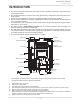
Owner's Guide Troubleshooting COMPONENTS DIAGRAM Case assembly Outdoor models Indoor models 052 052 003 007 004 713 052 001 004 717 002 001 702 704 006 702 008 005 052 052 704 050 002 050 Temperature controller Temperature remote controller Indoor models 723 724 056 722 51 Page
Owner's Guide Troubleshooting Computer board assembly 240 (T-H3J) and 340 (T-H3S) models 540 (T-H3) models 709 701 710 701 710 708 708 714 713 713 403 714 103 721 709 103 402 402 402 408 407 707 061 722 715 402 721 707 722 716 716 Surge box assembly 121 703 713 703 706 52 Page 053 709 063 715
Owner's Guide Components Diagram Burner assembly Burner assembly 101 104 115 053 053 709 108 107 401 106 116 053 110 062 109 111 712 112 117 053 114 102 103 105 113 065 708 054 150 Manifold Assembly 121 120 712 707 711 062 151 057 055 055 117 063 714 53 118 051 719 540 (T-H3) models 119 Page
Owner's Guide Components Diagram Water Way assembly 413 453 452 F 412 153 472 058 401 064 462 473 459 468 B 468 467 064 E E F D D 464 009 455 466 052 469 456 460 456 460 462 D C 403 458 458 A B Bypass section (540 (T-H3) models) 450 414 416 465 240 (T-H3J) and 340 463 466 (T-H3S) models 052 414 053 463 C 451 470 455 414 A 415 718 473 451 540 (T-H3) models 471 451 415 454 411 462 462 152 402 461 458 404 454 408 052 462 417 409 052 455 410 W
Owner's Guide Components Diagram PARTS LIST Item # 001 002 003 004 005 006 007 008 009 050 051 052 053 054 055 056 057 058 059 060 061 062 063 064 065 101 102 103 104 105 106 107 108 109 110 111 112 113 114 115 Part # Description Case assembly for Indoor models for Outdoor models Front cover for 240 and 340 Indoor (T-H3J-DV and T-H3S-DV) for 240 and 340 Outdoor (T-H3J-OS and T-H3S-OS) for 540 Indoor (T-H3-DV) for 540 Outdoor (T-H3-OS) Intake air port assembly Bracket Junction box Pow
Owner's Guide Parts List Item # 116 117 118 119 120 121 150 151 152 153 401 402 403 404 405 406 407 408 409 410 411 412 413 414 415 416 417 450 451 452 453 454 455 456 457 458 459 460 461 Part # Description Pressure port Combustion chamber tube Gas inlet Gas inlet ring Igniter plate Surge box plate O-ring P18 NBR (Black) O-ring P20 NBR (Black) Silicon ring for Outdoor models Exhaust port for Outdoor models Heat exchanger assembly for 240 and 340 Indoor (T-H
Owner's Guide Parts List Item # Part # Description 714 715 716 717 718 719 721 722 723 Fastener “16-25A” Fastener “6-15” Flat heater Drain tube Cold pipe for 240 (T-H3J) and 340 (T-H3S) models for 540 (T-H3) models Stainless heat exchanger out pipe Header connection Drain port Thermistor fixing plate Exhaust thermistor gasket Hi-limit switch for exhaust Gasket Computer board for 240 (T-H3J) models for 340 (T-H3S) models for 540 (T-H3) models Rubber grommet Surge box 120 VAC wire for Indoor models for Ou
Owner's Guide Output Temperature Chart OUTPUT TEMPERATURE CHART Chart is based on properly sizes gas line Output Hot Water GPM 240 (T-H3J) models Output Temperature vs. GPM (Max. 6.6 GPM) with Various Inlet Water Temperature 340 (T-H3S) models Output Hot Water GPM Output Temperature vs. GPM (Max. 8.0 GPM) with Various Inlet Water Temperature 540 (T-H3) models Output Hot Water GPM Output Temperature vs. GPM (Max. 10.
Owner's Guide Warranty LIMITED WARRANTY 1. General terms of limited warranty: This limited warranty gives you specific legal rights, and you may also have other rights which vary from State to State. The manufacturer will honor the warranty to the original retail buyer at the original location only, and it is not transferable.
Owner's Guide Warranty (3) Limited Labor Coverage • The manufacturer will provide for reasonable labor charges associated with warranty repairs or replacements within one (1) year from the date of purchase. The manufacturer will only pay directly to the service provider. • Warranty service must be performed by an authorized Service Representative. A list of authorized Service Representatives is available upon request.