
Install Instructions


Installation
28│Page
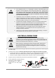
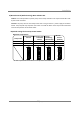
Thedarksquaresindicatethedirection
thedipswitchesshouldbesetto.
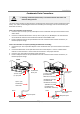
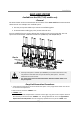
4.Betweenthe“PARENT”andthe“CHILD‐1”units
Connectthe“PARENTconnector”ofthe“PARENT”unittothe“[1]connector”ofthe“CHILD‐1”
unit.
5.Betweenthe“CHILD‐1”andthe“CHILD‐2”units
Connectthe“[2]connector”of the“CHILD‐1”unittothe“[1]connector”ofthe“CHILD‐2”unit.
6.Betweenthe“CHILD‐2”andthe“CHILD‐3”units
Connectthe“[2]connector”of the“CHILD‐2”unittothe“[1]connector”ofthe“CHILD‐3”unit.
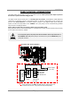
7.Makesurethe“3‐digit7‐seg.LED”ofalltheunits’computerboardsdisplaytheunit#.The
numberingsystemautomaticallyallocatestheunit#toeachwaterheaterin
theEasy‐Linksystem,
inaccordancewiththetablebelow.
Parentunit Unit#:1
Childunits Unit#:2,3and4
(A)520(T‐H2)Computerboard
(B)Basicdiagramofconnectionsamongthe520(T‐H2)models.
Rightbankof
dipswitches
Leftbankof
dipswitches
Whensettingaunittoa
“PARENT”unit,adjust
dipswitchNo.10onthe
rightbankof
dipswitchesonly
(
seedia
g
ram
)
.
Easy‐Linkconnectors
arenexttothe
com
p
uterboard.
3digit7‐Seg.LED
CHILD‐3unit
PARENT unit
CHILD‐1unit
CHILD‐2unit
Connectors
P
A
R
E
N
T
2
1
2
1
Communication cable
Connectors
P
A
R
E
N
T
2
1
2
1
O
F
F
O
N
1
2
3
4
5
6
7
8
Right bank
of Dipswitches
O
F
F
O
N
9
1
0
Connectors
P
A
R
E
N
T
2
1
2
1
Connectors
P
A
R
E
N
T
2
1
2
1
1
2
3
4
5
6
7
8
1
2
3
4
5
6
7
8
9
1
0
O
F
F
O
N
1
2
3
4
5
6
7
8
Right bank
of Dipswitches
O
F
F
O
N
9
1
0
1
2
3
4
5
6
7
8
1
2
3
4
5
6
7
8
9
1
0
O
F
F
O
N
1
2
3
4
5
6
7
8
Right bank
of Dipswitches
O
F
F
O
N
9
1
0
1
2
3
4
5
6
7
8
1
2
3
4
5
6
7
8
9
1
0
O
F
F
O
N
1
2
3
4
5
6
7
8
Right bank
of Dipswitches
O
F
F
O
N
9
1
0
1
2
3
4
5
6
7
8
1
2
3
4
5
6
7
8
9
1
0