
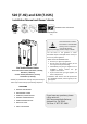
Install Instructions


Contents
2│Page
NOTE
Checktheratingplatetoensurethisproductmatchesyour
specifications.
In accordance with ANZI Z21.10.3, CO emission does not
exceed400PPMfornormalinput.
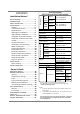
CONTENTS
SPECIFICATIONS
520 (T‐H2) and 320(T‐H2S)models
GasInput
520
(T‐H2)
models
Natural
Min:13,000Btu/h
Max:199,000Btu/h
Propane
320
(T‐H2S)
models
Natural
Min:13,000Btu/h
Max:180,000Btu/h
Propane
GasConnection ¾”NPT
WaterConnections ¾”NPT
CondensateDrainPort
Connection
½”NPT
WaterPressure* 15‐150psi
NaturalGas
Inlet Pressure
Min.5.0”WC
Max.10.5”WC
Propane
Inlet Pressure
Min.8.0”WC
Max.14.0”WC
ManifoldPressure**
520Direct
VentIndoor
(T‐H2‐DV)
Natural:3.2”WC
Propane:5.5”WC
520Outdoor
(T‐H2‐OS)
Natural:2.7”WC
Propane:4.6”WC
320Direct
VentIndoor
(T‐H2S‐DV)
Natural:2.5”WC
Propane:4.3”WC
320Outdoor
(T‐H2S‐OS)
Natural:1.9”WC
Propane:3.6”WC
Weight
73lbs.
(DirectVentIndoormodels)
71lbs.(Outdoormodels)
Dimensions H25.6”xW18.5”xD12.4”
Ignition ElectricIgnition
Electric
Supply 120VAC/60Hz
Consumption
Operationofthe
DirectVent
Indoormodels
152W
(1.27A)
Operationofthe
Outdoormodels
102W
(0.85A)
Standby
8.2W
(0.07A)
Freeze‐
Protection
207W
(1.73A)
SPECIFICATIONS………………………………...
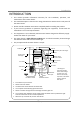
INTRODUCTION……………………………….…
SAFETYGUIDELINES…………….……………..
INSTALLATION………………………………..….
General………………………………………..…
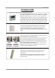
IncludedAccessories…………………..…
Optionalitems…………………………..…..
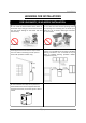
WarningforInstallations………..….....
High‐altitudeInstallations………………
Installationforoutdoormodels……..
Installationfordirectventindoor
models……………………………………………
VentingInstructions……………………....
GasSupply/GasPipeSizing………...…
WaterConnections……………..……….…
PressureReliefValve………………………
Condensatedrain…………………………..
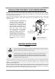
ElectricalConnections…………….........
RemoteControllerConnection…….…
PumpControlConnections………..……
PumpControlMode…………………….…
Easy‐LinkSystem…………………………....
APPLICATIONS...…………………………………
SpaceHeating……….………….……………
INITIALOPERATION..…………………….……
OPERATINGSAFETY……………………………
NORMALOPERATION…………………………
General………..……….………….……………
Temperaturesettings.…….…..…………
Flow……………………………………………….
FreezeProtectionSystem…….…………
MaintenanceandService………………
UnitDrainingandFilterCleaning……
TROUBLESHOOTING……..……………………
General………..……….………….……………
Errorcodes.…………………….…..…………
COMPONENTSDIAGRAM………………..…
PARTSLIST………………….………………………
OUTPUTTEMPERATURECHART……...…
LIMITEDWARRANTY…………………….……
2
3
4
5
6
6
7
8
9
9
10
10
17
19
20
20
22
23
24
25
27
31
31
33
34
36
36
36
38
38
39
39
40
40
42
44
47
50
51
Themanufacturerreservestherighttodiscontinue,orchangeat
anytime,specificationsordesignswithoutnoticeandwithout
incurringobligations.
InstallationManual
Owner’sGuide
*40psioraboveisrecommendedformaximumflow.
**TheManifoldPressureisthefactorysettingandgenerally
shouldnotneedadjustment.