
Install Instructions
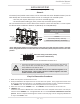

29 Page
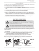
MULTI-UNIT SYSTEM
Multiple 510U (T-D2U) models can be combined for a Multi-Unit System, along with the multi-
unit controller (Parts 9008300005 (TM-MC02)) and remote controller (9008172005 (TM-RE40)).
Each set of multi-unit controller and remote controller can control from 2 units to 20 units
for commercial or residential applications. For a 20-unit system, the computer can modulate
between the usages of 15,000 BTU/h to 4.0 Million BTU/h.
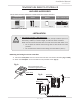
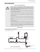
An individual cut-off switch is recommended for each unit in a Multi-Unit System for the purpose
of maintenance.
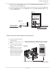
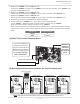
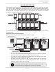
Multi-Unit System connection diagram
Multi-unit controller and temperature remote controller wiring:
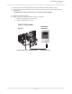
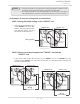
• The dark squares should not need adjustment.
• This is the connection diagram between 510U (T-D2U) and multi-unit controller
for 2 to 20 water heaters. Above is a sample for 3 water heaters.
• The multi-unit controller automatically allocates the unit # (1-20) to each water
heater that is part of the Multi-Unit System.
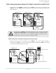
• In a Multi-Unit System, connect the “[1]” connector and the “[2]” connector with
the communication cable (refer to p. 26) or 18 gauge wire cables. The total cable
length can be up to 250 ft. (76.2 m) long.
For detailed instructions on the multi-unit controller, refer to the
instructions that are packaged with the multi-unit controller.
OFF
ON
1
1
1
2
2
2
PARENT
PARENT
PARENT
1
2
3
4
5
6
Connectors Connectors Connectors
OFF
ON
OFF
ON
Lower bank of
DIPswitches
Lower bank of
DIPswitches
Lower bank of
DIPswitches
1
2
3
4
5
6
1
2
3
4
5
6
Communicaon cable
Remote controller cable
Unit 1
Unit 2 Unit 3
Remote controller
9008172005 (TM-RE40)
Terminals for
water heaters
9008300005
(TM-MC02)
Remote controller
terminals
9008300005
(TM-MC02)
510U
(T-D2U)
Cold IN
Hot Out
Installaon
Installaon Manual