On-Demand Water Heater Installation Manual and Owner’s Guide ANSI Z21.10.3 and CSA 4.3 510U (T-D2U) model only Models • 110U Indoor (T-KJr2U-IN) • 110U Outdoor (T-KJr2U-OS) • 310U Indoor (T-K4U-IN) • 310U Outdoor (T-K4U-OS) • 510U Indoor (T-D2U-IN) • 510U Outdoor (T-D2U-OS) If the information in these instructions is not followed exactly, a fire or explosion may result causing property damage, WARNING personal injury or death.
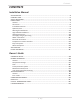
Contents CONTENTS Installation Manual SPECIFICATIONS........................................................................................................................... 4 INTRODUCTION........................................................................................................................... 5 SAFETY GUIDELINES..................................................................................................................... 6 INSTALLATION..............................................
Installation Manual Installation Manual CONGRATULATIONS Congratulations and thank you for choosing our tankless water heater. Before use, we recommend that you read through this safety manual carefully. Please refer to the back of the manual for details about the warranty. Keep this manual for future reference. If you lose the manual, contact the manufacturer or your local distributor.
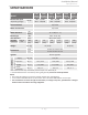
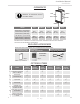
Installation Manual Specifications SPECIFICATIONS 110U Indoor Model 110U Outdoor 310U Indoor 310U Outdoor BTU/h Min.: 15,000 Max.: 140,000 Min.: 15,000 Max.: 190,000 Gas Connection 3/4" NPT Water Connections 3/4" NPT Water Pressure* Natural gas Inlet Pressure Manifold Pressure** Natural Gas Weight psi (Mpa) " W.C. (kPa) " W.C. (Pa) Min.: 15,000 Max.: 199,000 15 - 150 (0.1 - 1) 1.8 (448) 1.5 (373) lbs. (kg) Dimensions Min. 5.0 (1.24) Max. 10.5 (2.61) 3.0 2.9 (747) (722) 37 (16.
Installation Manual Introduction INTRODUCTION • This manual provides information necessary for the installation, operation, and maintenance of the water heater. • The model description is listed on the rating plate which is attached to the side panel of the water heater. • Please read all installation instructions completely before installing this product. • If you have any problems or questions regarding this equipment, consult the manufacturer or its local representative.
Installation Manual Safety Guidelines SAFETY GUIDELINES SAFETY DEFINITION DANGER WARNING CAUTION Indicates an imminently hazardous situation which, if not avoided, will result in death or serious injury. Indicates an imminently hazardous situation which, if not avoided, could result in death or serious injury. Indicates an imminently hazardous situation which, if not avoided, could result in minor or moderate injury. GENERAL 1.
Installation Manual Installation INSTALLATION GENERAL 1. Follow all local codes, or in the absence of local codes, follow the most recent edition of the National Fuel Gas Code: ANSI Z223.1/NFPA 54 in the USA or CAN/CSA B149.1 Natural Gas Installation Code in Canada. 2. All gas water heaters require careful and correct installation to ensure safe and efficient operation. This manual must be followed exactly. Read the “Safety Guidelines” section. 3. The manifold gas pressure is preset at the factory.
Installation Manual Installation • Installation and service must be performed by a qualified installer (for example, a licensed plumber or gas fitter), otherwise the warranty will be void. WARNING • The installer (licensed professional) is responsible for the correct installation of the water heater and for compliance with all national, state / provincial, and local codes. • The manufacturer does not recommend installing the water heater in a pit or location where gas and water can accumulate.
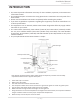
Installation Manual Installation CLEARANCES Top Back Side Maintain all clearances around the water heater. Front Side Bottom Model Top Bottom Front Back Sides 110U Indoor (T-KJr2U-IN)* 310U Indoor (T-K4U-IN)* 510U Indoor (T-D2U-IN)* 12 in. (305 mm) 12 in. (305 mm) 4 in.** (102 mm) 0.5 in. (13 mm) 3 in. (76 mm) 110U Outdoor (T-KJr2U-OS) 36 in. 310U Outdoor (T-K4U-OS) (914 mm) 510U Outdoor (T-D2U-OS) 12 in. (305 mm) 24 in. (610 mm) 0.5 in. (13 mm) 3 in.
Installation Manual Installation 1. 4” Backflow preventer and F-F adaptor: 9007996005 There are two functions available for this adaptor, which can be connected with the water heater and NovaVent venting line and prevents the backflow of air through the exhaust vent. This helps prevent harmful exhaust gases from entering the home, as well as helping to prevent the unit from freezing in areas where cold air can be blown or drawn into the exhaust system.
Installation Manual Installation WARNING FOR INSTALLATIONS FOR YOUR SAFETY, READ BEFORE INSTALLATION: Do not install the heater where water, debris or flammable vapors may get into the flue terminal. This may cause damage to the heater and void the warranty. Do not have the vent terminal pointing toward any opening into a building. Do not locate your heater in a pit or location where gas and water can accumulate. Prohibited Prohibited Do not install this water heater under an overhang less than 3 ft.
Installation Manual Installation HIGH-ALTITUDE INSTALLATIONS Check the elevation where your water heater is installed. Set DIPswitches shown in the table below depending on the altitude. Indoor models DIPswitches Altitude 0 to 2,000 ft. (DEFAULT) ON 110U (T-KJr2U) and 310U (T-K4U) models 510U (T-D2U) model (Lower bank of DIPswitches) Outdoor models OFF 510U (T-D2U) model (Lower bank of DIPswitches) 3,000 to 5,000 ft. 1 2 3 4 5 6 7 8 9 10 ON OFF ON 1 2 3 4 5 6 7 8 9 10 OFF 5,000 to 7,500 ft.
Installation Manual Installation VENTING INSTRUCTIONS For indoor models -General• Improper venting of this appliance can result in excessive levels of carbon monoxide which can result in severe personal injury or death. • Improper installation can cause nausea or asphyxiation, severe injury or death from carbon monoxide and flue gases poisoning. Improper installation will DANGER void product warranty. When installing the vent system, all applicable national and local codes must be followed.
Installation Manual Installation -Vent length and No. of ElbowsThis is a Category III appliance and must be vented accordingly. The vent system must be sealed airtight. All seams and joints without gaskets must be sealed with high heat resistant silicone sealant or UL listed aluminum adhesive tape having a minimum temperature rating of 350 °F (177 °C). For best results, a vent system should be as short and straight as possible.
Installation Manual Installation Venting Illustrations- For the 110U Indoor (T-KJr2U-IN), 310U Indoor (T-K4U-IN) and 510U Indoor (T-D2U-IN) models For details of the optional items, refer to the Installation manual for each Optional item.
Installation Manual Installation -Vent termination clearancesINSIDE CORNER DETAIL V Vent terminal X Air supply inlet V Area where is not permitted G H A D E V B B B C V F V FIXED ED CLOS E BL A OPER V L V ED ABLE FIXLOSED C OPER V B B V I X M V X K J A Gas meter / regulator B A Canada Direct-vent and other than Direct-vent Directvent 1 foot 1 foot 1 foot 3 feet 1 foot 4 feet from below or side opening. 1 foot from above opening.
Installation Manual Installation -For sidewall terminations2 ft. 1 ft. (305 mm) (610 mm) min min 1 ft. (305 mm) min Exhaust termination Inside corner 2 ft. 1 ft. (305 mm) (610 mm) min min 1 ft. (305 mm) min Combined intake and exhaust termination Exhaust termination 3 ft. (915 mm) min Inside corner For multiple sidewall exhaust terminations (e.g. multiunit systems), an exhaust termination must be at least 1 ft. (305mm) away from another exhaust termination.
Installation Manual Installation GAS SUPPLY AND GAS PIPE SIZING -General- CAUTION • Check that the type of gas matches the rating plate first. • Ensure that any and all gas regulators used are operating properly and providing gas pressures within the specified range shown below. Excess gas inlet pressure may cause serious accidents. • Conversion of this unit from natural gas to propane or vice versa will void all warranty. Contact your local distributor to get the correct unit for your gas type.
Installation Manual Installation -Natural Gas Supply PipingMaximum delivery capacity of cubic feet of gas per hour of IPS pipe carrying Natural Gas with 0.60 specific gravity based on pressure drop of 0.5" W.C. Based on energy content of 1,000 BTU/Cubic ft.: The water heater requires 140 Cubic ft./hr for the 110U (T-KJr2U) model, 190 Cubic ft./hr for the 310U (T-K4U) model, and 199 Cubic ft./hr for the 510U (T-D2U) model.
Installation Manual Installation -Measuring inlet gas pressure1. Turn off all electric power to the water heater if service is to be performed. 2. Turn the manual gas valve located on the outside of the unit clockwise to the off position. The water heater cannot perform properly without sufficient inlet gas pressure. Below are instructions on how to check the inlet gas pressure. THIS IS ONLY TO BE DONE BY A LICENSED PROFESSIONAL. 1. Shut off the manual gas valve on the gas supply line. 2.
Installation Manual Installation -Pressure relief valveThe water heater has a high-temperature shutoff switch built in as a standard safety feature (called a Hi-Limit switch) therefore a “pressure only” relief valve is required. • This unit does not come with an approved pressure relief valve. • An approved pressure relief valve must be installed on the hot water outlet. • The pressure relief valve must conform to ANSI Z21.22 or CAN 1-4.4 and installation must follow local codes.
Installation Manual Installation TEMPERATURE REMOTE CONTROLLER -INCLUDED ACCESSORIESCheck that these items below are included with the remote controller. Temperature remote controller* Screws Qty: 1 Manual Qty: 2 Qty: 1 Remote controller cable Qty: 1 *9009069005 (TM-RE42) -INSTALLATION- CAUTION • This remote controller is NOT waterproof Do not install in high temperature environments, steamy conditions (such as a bath room), outdoors, in direct sunlight, or within the reach of children.
Installation Manual Installation 3. Tighten the two "Fork terminals" beneath the two "Remote controller terminal" screws on the back of the main body. (Fig. C-1) 4. Cut out the inlet for the remote controller cable from the bottom of the main body. (Fig. C-2) 5. Place the “Main body” back on the "Back plate", with the "Remote controller cable" running out of the bottom inlet. Fig. C-1 Remote controller terminals Fig.
Installation Manual Installation 5. Pull the remote’s wires through the hole at the bottom of the water heater’s casing. 6. Properly attach the remote’s wires to the remote controller terminal on the computer board (No polarity). * Do NOT jump or short-circuit the wires, or computer will be damaged. 7. Replace Front Cover securely. 8. Wires used for the remote controller connection must be: • Minimum 20 gauge wire (No polarity) • Maximum 400 ft. (122 m) long 510U (T-D2U) model 9009069005 (TM-RE42) Fig.
Installation Manual Installation EASY-LINK SYSTEM (Available on the 510U (T-D2U) model only) -GeneralThe 510U (T-D2U) model water heaters can be connected with other allowable heaters (see the table below) with communication cables to work as a multiple-unit manifold system. • The Easy-Link System allows up to 4 units to manifold together. • A communication cable (gray color) comes with each 510U (T-D2U) model. You can manifold from 2 to 4 units without the need for a multi-unit controller.
Installation Manual Installation 5. Between the “PARENT” and the “CHILD-1” units: Connect the “PARENT” connector of the “PARENT” unit to the “1” connector of the “CHILD-1” unit using the supplied linking cable. 6. Between the “CHILD-1” and the “CHILD-2” units: Connect the “2” connector of the “CHILD-1” unit to the “1” connector of the “CHILD-2” unit. 7. Between the “CHILD-2” and the “CHILD-3” units: Connect the “2” connector of the “CHILD-2” unit to the “1” connector of the “CHILD-3” unit. 8.
Installation Manual Installation NOTICE • A remote controller is not required for an Easy-Link System, however, it does provide for more temperature options and ease of maintenance. • If a remote controller is used, the temperature on all the units in the system will automatically be set to the same temperature that is set on the remote. (C) Examples of incorrect settings and /or connections CASE 1: Wrong DIPswitch setting on the "PARENT" unit • Unless you change DIPswitch No.
Installation Manual Installation CASE 3: Wrong connections between the "CHILD-1" unit and the "CHILD-2" unit • If you connect the “PARENT” connector of the “CHILD-1” unit to the “1” connector of the “CHILD-2” unit, the “CHILD-2” unit will operate as an individual unit, and will not be part of the Easy-Link System.
Installation Manual Installation MULTI-UNIT SYSTEM Multiple 510U (T-D2U) models can be combined for a Multi-Unit System, along with the multiunit controller (Parts 9008300005 (TM-MC02)) and remote controller (9008172005 (TM-RE40)). Each set of multi-unit controller and remote controller can control from 2 units to 20 units for commercial or residential applications. For a 20-unit system, the computer can modulate between the usages of 15,000 BTU/h to 4.0 Million BTU/h.
Installation Manual Applications APPLICATIONS -Space-Heating Applications• In order to purge air in water pipes within a closed-loop system, an air vent and air separator should be installed in the system. Required circulation flow rates are labeled next to each application diagram. These flow rate requirements must be followed.
Installation Manual Installation -Dual-purpose hot water heating(Domestic and Space Heating): Diagrammatic layout of radiant heating and domestic water heater per Mass. code. All water piping should be insulated in accordance with 780 CMR (Massachusetts energy code) Atmospheric vacuum breaker Thermostatic mixing valve Heating Coil (used with air-handler) Check valves 50’-0” maximum distance from water heater to fan coil.
Installation Manual Initial operation INITIAL OPERATION FOR YOUR SAFETY, READ BEFORE OPERATING • Check the GAS and WATER CONNECTIONS for leaks before firing unit for the first time. • Open the main gas supply valve to the unit using only your hand to avoid any spark. Never use tools. If the knob will not turn by hand, do not try to force it; call a qualified service technician. Forced repair may result in a fire or explosion due to gas leaks.
Owner's Guide Owner's Guide CONGRATULATIONS Congratulations and thank you for choosing our tankless water heater. Before use, we recommend that you read through this safety manual carefully. Please refer to the back of the manual for details about the warranty. Keep this manual for future reference. If you lose the manual, contact the manufacturer or your local distributor. When you call, please tell us the product name and the serial number of your unit written on the rating plate of the water heater.
Owner's Guide Operating Safety OPERATING SAFETY FOR YOUR SAFETY READ BEFORE OPERATING WARNING: If you do not follow these instructions exactly, a fire or explosion may result causing property damage, personal injury or loss of life. A. This water heater does not have a pilot. It is equipped with an ignition device that automatically lights the burner. Do not try to light the burner by hand. B. BEFORE OPERATING smell all around the water heater area for evidence of leaking gas.
Owner's Guide Operating Safety DANGER Vapors from flammable liquids will explode and catch fire causing death or severe burns. Do not use or store flammable products such as gasoline, solvents or adhesives in the same room or area near the water heater. Keep flammable products: 1. Far away from heater 2. In approved containers 3. Tightly closed 4. Out of children's reach Vapors: 1. Cannot be seen 2. Vapors are heavier than air 3. Go a long way on the floor 4.
Owner's Guide Normal Operation NORMAL OPERATION REMOTE CONTROLLER The illustration below shows an example of the display. The exact display may differ from examples. Display for Temperature "INFO" Button When the STAND BY LED is ON, the hot water temperature will be displayed. Each time the button is pressed, the operation mode is selected in the sequence of the following.
Owner's Guide Normal Operation TEMPERATURE SETTINGS -Set temperatureOperation Screen 1. Turn on the 120 VAC power supply to the unit (the water heater or the multi-unit controller). 2. Press the "ON/OFF" button on the controller in order to turn the controller on. 3. When ON, the STAND BY LED is lit. 4. It shows the set temperature on its display as shown in the picture on the right. (EX.: 120 °F) (EX.
Owner's Guide Normal Operation ADDITIONAL FEATURES -Information modeYou can get some information about the water heater condition by pressing the "INFO" button. For more information, follow the procedures below: Operation Screen 1. First of all, inlet water temperature will be displayed on the remote controller by pressing the "INFO" button. Inlet water temperature 2. Outlet water temperature will be displayed on the remote controller by pressing the "INFO" button. Outlet water temperature 3.
Owner's Guide Normal Operation TEMPERATURE SETTINGS ON THE PCB (WITHOUT REMOTE CONTROLLER) There are 2 preset temperatures (120 °F (50 °C) and 140 °F (60 °C)) that you can select from by changing the DIPswitch settings on the computer board without the remote controller. See the table below. When the remote controller is in normal operation, the set temperature of the remote controller is given priority over the set temperature of the DIPswitch settings.
Owner's Guide Normal Operation FLOW • The flow rate through the water heater is limited to a maximum of 6.6 GPM (25 L/min) for the 110U Appliance/Use (T-KJr2U) model, 8.0 GPM (30 L/min) for the 310U (T-K4U) model, and 10.0 GPM (38 L/min) for the Lavatory Faucet 510U (T-D2U) model. Bath Tub • The temperature setting, along with the supply Shower temperature of the water will determine the flow rate output of the unit. Kitchen Sink • Please refer to the temperature vs.
Owner's Guide Normal Operation MAINTENANCE AND SERVICE WARNING Turn off the electrical power supply and close the manual gas shutoff valve and the manual water control valve before servicing. • • • • • Clean the cold-water inlet filter. (Refer to Unit draining and filter cleaning section in this page.) Be sure that all openings for combustion and ventilation air are not blocked. The venting system should be checked annually for any leaks, corrosion, blockages or damage.
Owner's Guide Troubleshooting TROUBLESHOOTING PROBLEM GENERAL SOLUTIONS WATER CONNECTIONS TEMPERATURE and AMOUNT OF HOT WATER It takes long time to • The time it takes to deliver hot water from the water heater to your get hot water at the fixtures depends on the length of piping between the two. The longer fixtures. the distance or the bigger the pipes, the longer it will take to get hot water.
Owner's Guide Troubleshooting EASY-LINK SYSTEM 510U (T-D2U) model only Remote controller WATER HEATER PROBLEM SOLUTIONS Unit does not ignite when water goes through the unit. • • • • • • Is the flow rate over 0.5 GPM (1.9 L/min)? (p. 36) Check for the filter on cold water inlet. (p. 41) Check for reverse connection and cross connection. If you use the remote controller, is the power button turned on? Check if the inlet temperature is too high. The fan motor is This is normal.
Owner's Guide Troubleshooting ERROR CODES -General• The units have self-diagnostic function for safety and convenience when troubleshooting. • If there is a problem with the installation or the unit, the error code will be displayed on the remote controller. • Consult with the table on the following pages for the description of each error code.
Owner's Guide Troubleshooting -Fault Analysis of Error CodesIf the error code is displayed on the computer board of the water heater or remote controller, please check the following. After checking, consult with the manufacturer.
Owner's Guide Troubleshooting Remote Green LED 391 Two Times 441 Two Times 510 Six Times 551 Six Times 611 Four Times 651 Four Times 661 Four Times 701 711 One Time One Time 721 Six Times 741 N/A 761 N/A 991 Five Times Malfunction description Diagnosis Air-fuel ratio rod • Check for connection/breakage of wires (Part #709) failure and/or soot on the AFR rod (Part #108).
Owner's Guide Components Diagram COMPONENTS DIAGRAM Case assembly Outdoor model Indoor model 052 003 052 004 007 001 001 704 006 002 005 702 717 051 052 704 002 050 Temperature remote controller 721 47 Page
Owner's Guide Components Diagram Computer board assembly 110U (T-KJr2U) and 310U (T-K4U) models 711 701 510U (T-D2U) model 711 708 701 705 705 709 708 408 407 103 714 709 403 103 402 402 402 715 402 714 707 061 715 707 716 716 Surge box assembly 121 053 703 705 704 706 705 48 Page
Owner's Guide Components Diagram Burner assembly Burner assembly 101 116 123 062 108 720 110 060 109 053 105 060 709 401 117 107 106 103 104 711 111 711 053 060 113 114 115 056 122 052 060 713 054 112 116 102 714 053 117 708 053 Manifold assembly 055 057 150 153 119 151 055 707 118 154 053 401 052 711 401 062 152 719 063 Exhaust section (Outdoor model) 49 Page
Owner's Guide Components Diagram Water Way assembly 463 Bypass section (510U (T-D2U)model) 413 453 403 452 458 456 460 A 462 B 401 412 510U (T-D2U) model 459 058 A 454 411 B 451 D 414 To Water inlet section 451 To Water outlet section C 456 460 454 408 D 460 455 402 461 458 409 450 414 C 456 414 404 052 410 406 Water outlet section 457 059 454 407 405 Water inlet section 50 Page 415
Owner's Guide Parts List PARTS LIST Item # 001 002 003 004 005 006 007 050 051 052 053 054 055 056 057 058 059 060 061 062 063 101 102 103 104 105 106 107 108 109 110 111 112 113 114 115 116 117 118 119 Part # Description Case assembly for Indoor models for Outdoor models Front cover for 110U and 310U Indoor (T-KJr2U-IN and T-K4U-IN) for 110U and 310U Outdoor (T-KJr2U-OS and T-K4U-OS) for 510U Indoor (T-D2U-IN) for 510U Outdoor (T-D2U-OS) Air blockage plate for Indoor models Bracket Junction box Power s
Owner's Guide Parts List Item # 121 122 123 150 151 152 153 154 401 402 403 404 405 406 407 408 409 410 411 412 413 414 415 450 451 452 453 454 455 456 457 458 459 460 461 462 463 Part # Description Surge box plate Gasket Gasket O-ring P18 NBR (Black) O-ring P20 NBR (Black) Silicon ring for Outdoor models Rain protection plate in Exhaust chamber for Outdoor models Exhaust port for Outdoor models Heat exchanger assembly for 110U and 310U Indoor (T-KJr2U-IN and T-K4U-IN) for 110U and 310U Outdoor (T-KJr2U-
Owner's Guide Parts List Item # 701 702 703 704 705 706 707 708 709 711 713 714 715 716 717 719 720 721 Part # Description Computer board for 110U (T-KJr2U) model for 310U (T-K4U) model for 510U (T-D2U) model Rubber grommet for Indoor models Surge box 120 VAC wire for Indoor models for Outdoor models Switch wire 120 VAC Power ON-OFF switch Remote controller wire for 110U (T-KJr2U) and 310U (T-K4U) models for 510U (T-D2U) model Gas valve wire Flame rod wire for 110U (T-KJr2U) and 310U (T-K4U) models Flame
Owner's Guide Output Temperature Chart OUTPUT TEMPERATURE CHART Chart is based on properly sized gas line Output Hot Water GPM 110U (T-KJr2U) model Output Temperature vs. GPM (Max. 6.6 GPM) with Various Inlet Water Temperature Incoming Temp. (°F) Set Temp. (°F) 310U (T-K4U) model Incoming Temp. (°F) Output Hot Water GPM Output Temperature vs. GPM (Max. 8.0 GPM) with Various Inlet Water Temperature Set Temp. (°F) Output Hot Water GPM 510U (T-D2U) model Output Temperature vs. GPM (Max. 10.
Owner's Guide Warranty LIMITED WARRANTY 1. The manufacturer warrants this product against defects in materials or workmanship as described in this document if installed within the United States or Canada.
Owner's Guide Warranty • Freeze damage that occurs without taking proper preventive measures as described in the installation manual. • Condensate damage due to improperly installed or lack of a condensate trap (drain). • Any product not installed in compliance with all applicable local & provincial codes, ordinances, and good trade practices.