
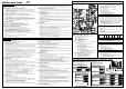
T-D2 Parts List

Iftheerrorcodeisindicatedonthe7‐Seg‐LEDonthePCB(Part#701)ofthewaterheater(and/or
theremotecontroller),refertoSectionB.
<<Ittakeslongtimetogethotwateratthefixtures>>
・ Thetimeittakestodeliverhotwaterfromthewaterheatertoyourfixturesdependson
thelengthofpipingbetweenthetwo.Thelongerthedistanceorthebiggerthepipes,
thelongeritwilltaketogethotwater.
・ Ifyouwouldliketoreceivehotwater
toyourfixturesquicker,youmaywanttoconsidera
hotwaterrecirculationsystem.
<<Thewaterisnothotenoughorturnscoldandstayscold>>
・ Comparetheflowandtemperature.Refertothe“Outputtemperaturechart”ofthe
installationmanual.
・ Checkcrossplumbingbetweencoldwaterlinesandhotwaterlines.
・ Checkifthegassupplyvalvefullyopen,thegaslinesizedproperlyandthegassupplies
pressureenough.Refertothe“Gas
supplyandgaspipesizing”oftheinstallationmanual.
・ Checkthesettemperature,andchangethedipswitchsetting.RefertoSectionD.
・ Referto“Watercircuit”inthissection.
<<Thewateristoohot>>
・ Checkthesettemperature,lowersettingtemperature.
<<Thehotwaterisnotavailablewhenafixtureisopened>>
・ Refertothe“Powersupplycircuit”and“Watercircuit”inthissection.
<<Fluctuationinhotwatertemperature>>
・ Checkifthefilteronthecoldwaterinletcleaned.(Part#406)
・ Checkifthegaslinesizedproperlyandthesupplygaspressuresufficient.
・ Checkforcrossconnectionbetweencoldwaterlinesandhotwaterlines.
・ Referto“Watercircuit”inthissection.
<<Unitdoesnotignitewhenwatergoesthroughthewaterheater>>
・ Refertothe“Powersupplycircuit”and“Watercircuit”inthissection.
・ Ifyouusetheremotecontroller,turnthepowerbuttononandthenthegreenLEDwill
lightup.
・ Checkifthefilteronthecoldwaterinletcleaned.(Part#406)
・ Referto“Watercircuit”in
thissection.
B.Errorcodes
031:Incorrectdipswitchsetting
・ CheckthedipswitchsettingsonthePCB.RefertoSectionD.
101:Warningforthe“991”errorcode
・ Checkthegastypeof thewaterheater.Ifit’swronggastypemodel,replacethewater
heatertocorrectone.
・ Checkifthereisanyblockage(Forexample,Dampersticking,VentFlapsinstalledonthe
terminator,Snowbuild uparoundterminator,Installedinacloset(Noventilationorlack
of combustion air)) in the intake air and/or exhaust. Refer to the “Vent termination
clearances”oftheinstallationmanual.
・ If the water heater is installed as a direct‐vent system, check whether there is enough
distancebetween the intake air terminal and the exhaust terminal. Refer to the “Vent
termination
clearances”oftheinstallationmanual.
・ Checkifthetotalventlengthdoesn’texceed50ftandthe#ofelbowsislessthan5Ea.
・ Check the altitude/elevation of area of where the water heater installed. Refer to the
“High‐altitudefunction”oftheSectionD.Andchangethedipswitch
settings.
・ Check if there is grease and/or dirt in the burner (Part #101) and the fan motor (Part
#103),especiallyifthewaterheaterhasbeeninstalledinacontaminatedarea.
・ Checkifthereisdustandlintinheatexchanger.
・ Checkthemanifoldpressureofthewaterheater.
Refertoinstallationmanual.
111:Ignitionfailure
1. Checkgassupplyandinletgaspressure.
2. CheckiftheHi‐limitswitch(Part#412)isproperlyfunctioning.
3. Check for connection/breakage of wires (Part #413, 708, 709, 712), burn marks on the
computer board (Part #701), and/or soot on the flame rod (Part #108). And then if
O.H.C.F
(Part#413)isbreakage,Consultthemanufacturer.
4. Checkifthereisabuzzingsparkignitionsoundcomingfromtheburner(Part#101)when
waterheaterpreparesforcombustion.
5. Listen for the double “clunk” sound coming from the gas valve assembly (Part #102)
whenwaterheatergoesintocombustion.
6. (Onlynosparkingand/orkicksound)Checkvoltageoneachwiretogasvalvesassembly
(Part#102)and/ortheigniter(Part#711).Refertothe“AppendixA”inSectionC.
*Nosparkingsound >>>>>Refertothe#1at“AppendixA”inSectionC.
*Nokicksound >>>>>Refer
tothe#2at“AppendixA”inSectionC.
7. Checkifthereisleakingfromheatexchanger(Part#401)
8. Checkifthereisdustandlintinnozzlesofthemanifold(Part#102).
9. Checkcurrentontheflamerod(Part#108).Refertothe #3at“Appendix
A”inSectionC.
121:Lossofflame
1. Checkgassupplyandinletgaspressure.
2. CheckiftheHi‐limitswitch(Part#412)isproperlyfunctioning.
3. Checkfor connection/breakageofwires(Part#413,708,709, 712),burnmarksonthe
computer board (Part #701), and/or soot on the flame rod (Part #108). And then if
O.H.C.F
(Part#413)isbreakage,Consultthemanufacturer.
4. Checkifthereisleakagefromheatexchanger(Part#401).
5. Checkifthereisdustandlintinnozzlesofthemanifold(Part#102).
6. Checkcurrentontheflamerod(Part#108).Refertothe#3at“AppendixA”in
SectionC.
M
M
a
a
i
i
n
n
t
t
e
e
n
n
a
a
n
n
c
c
e
e
s
s
h
h
e
e
e
e
t
t
6
6
2
2
S
S
1
1
0
0
1
1
‐
‐
3
3
A.Troubleshooting
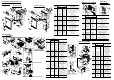
C. WiringDiagramandcheckpointoftheWaterheater
Therightbankhassettingsforthree
functions,shownbelow.
<Rightbankofdipswitches>
311,321,331:Disconnected/short‐circuitedthermistor
・
Checkforconnection/breakageofwiresand/ordebrisonthermistor(Part#407,408,411,716).
・ Checkthermistorresistance.Refertothe“AppendixD”inSectionC.
391:Air‐fuelRatioRodfailure
・
Checkforconnection/breakageofwires(Part#709)and/orsootontheAFRrod.(Part#108)
.
441:FlowSensorfailure(OnlyEasy‐Linksystem)
・ Check for connection/breakage of wires and/or debris on the flow sensor impeller (Part
#402,717).
510:AbnormalMainandSolenoidGasValve
・ Check for connection/breakageofwires(Part#708)and/orburnmarks on the computer
board(P art#701).
・ Resetpowersupplyofthewaterheater.
・ Check voltage on the each valve on the gas valves assembly (Part #102). Refer to the
“AppendixC”inSectionC.
611:Fanmotorfault
・ Checkforconnection/breakageofwires,dustbuildupinthefanmotor(Part#103)and/or
burnmarksonthecomputerboard(Part#701).
・ Checkforfrozen/corrosionofconnectorsofthefanmotor(Part#103).
・ Check voltagebetweenbluewireand eachwireofthefanmotor(Part#103), and check
resistancebetweenwhitewireandredwire.Refertothe“AppendixB”inSectionC.
651:Flowadjustmentvalvefault(OnlyEasy‐Linksystem)
・ Inspect the flow adjustment valve (Part #402), for connection/breakage of wires (Part
#718),lockedmotordriveduetoscalebuildup,and/orwaterleakage.
・ Checkvoltagebetweenblackwireandredwire.Refertothe“AppendixF”inSectionC.
701:Computerboardfault
・ Check for connection/breakageofwires(Part#714)and/orburnmarks on thecomputer
board(P art#701).
721:Falseflamedetection
1. Cleantheflamerod(Part#108).
2.
Forindoormodels,checkifcondensatedrainisinstalledontheventcollarofthewaterheater.
3. Checkifthereisleakingfromheatexchanger(Part#401).
741:Miscommunicationbetweenwaterheat er andremotecontroller
1.
Checkthemodeltypeoftheremote controller.ModelNo.9007603005(TM‐RE30)isthe
correctone
.
2. Inspect the connections between the water heater and remote controller. Refer to the
“Remotecontrollerconnections”oftheInstallationmanual.
3. Checkthepowersupplyofthewaterheater.
4. Ifthiserrorcodeappearsonlythe7‐SegLEDonthePCB(Part#701),checkthevoltageon
the
remotecontrollerterminalonthePCB.Refertothe“AppendixE”inSectionC.
5. Ifthiserrorcodeappearsonlyremotecontroller,replacethePCB(Part#701).
6. IfthiserrorcodeappearsboththePCB(Part#701)an dtheremotecontroller,replacethe
remotecontroller.
761:
MiscommunicationbetweenParentunitandChildunitsforEasy‐linksystem
・ Checkiftheconnectionsbetweentheparentunitandthechildunitsarecorrect.Referto
“Easy‐Linksystem”sectionintheInstallationmanual.
991:Imperfectcombustion
・ Refertothe“101”errorcodeinthissection.
<<Thefanmotorstillspinningafteroperationhasstopped>>
・ Thisisnormal.Afteroperationhasstopped,thefanmotorkeepsrunnin gfrom15to70
secondsinordertore‐ignitequickly,aswellaspurgealltheexhaustgasoutoftheflue.
<<Abnormalsoundfromwaterheater>>
・ Anabnormalsoundfromthewaterheatersiscausedbynotenough airsupplyorwrong
installations.Thewaterheaterneedsmorecombustionair.Refertothe“101”errorcode
inthesectionB.
<<Powersupplycircuit>>
1. If the remote controller installed,press the “ON/OFF” button of the remote controller,
andmakesurethatthegreenLEDonthe“ON/OFF”buttonoftheremotecontrollerislit.
Restartthewaterheater.
2. Check if that the 7‐SegLED on the PCB (Part #701) of the water
heaterislit. If so, the
power supply circuit of the water heater is under normal condition. Next, refer to the
“Watercircuit ”inthissection.
3. Checkthefuseonthesurgebox(Part#703),andifithasabrownspot,needtoreplaceit.
4. Checkthe
powersupply,andmakesurethatthewaterheaterhas120VAC.
5. If the 7‐Seg LED on the PCB (Part #701) isn’t lit, some electrical parts can be broken.
Consultthemanufacturer.
<<Watercircuit>>
1. Ifyou set theremotecontroller,turnthe powerbuttononandthenthegreenLEDwill
lightup.
2. Openall hot water faucets, and makesurethatthere is enough water flow. This water
heaterneedsatleast0.5GPMwaterflow(atthedefaultsettemperature)to
operate.
3. Checkforreverseconnectionandcrossconnection.
4. Checkifthefilteronthecoldwaterinletcleaned.(Part#406)
5. Checkifthereisnodebrisorobstructiononthefixtures.
6. Check if water ways in the water heater are frozen. If so, unfreezethem. And
refer to
installationmanualtoprotectyourwaterheaterfromfreeze.
7. Checkiftheinletwaterpressureishigherthan40psi.Andifit’slowerthan40psi,need
toincreasethepressure.
8. Checkforconnectionsandbreakageofwires(Part#402).
9. Checkif themotordrive
oftheflowadjustmentvalve(Part#402)islockedduetoscale
buildup,and/orwaterleakage.Consultthemanufacturer.
<Leftbankofdipswitches>
Leftbank
Rightbank
The left bank has certain sp ecial functions
andgenerallyshouldnotneedadjustment.
AppendixD(Forerrorcode311,321and331)
・ Mixingthermistor(FindthemarkingofNo.113ontheconnector)
Checkpoint“E1”
・ Outputthermistor(FindthemarkingofNo.12ontheconnector)
Checkpoint“E2”
・ Inlet thermistor (Find the marking of No.42 on the connector)
Checkpoint“E3”
Checkresistancebetweenblackwireandblackwire.
Temp e rature
°F
50 59 68 77 86 95
°C 10 15 20 25 30 35
Resistance kΩ 15.4 12.6 10.3 8.5 7.0 5.9
Allcheckpointsarenormal?
Yes>>ReplacethePCB.(Part#701)
No>>Replacethewrongthermistor.(Part#407,408,411)
AppendixE(F orerrorcode741)
Refertocheckpoint“F”onthewiringdiagramabove.
CheckvoltageontheremotecontrollerterminalonthePCB.
(Normal:11to15VDC)
Thischeckpointisnormal?
Yes>>Replacetheremotecontroller.
No>>ReplacethePCB.(Part#701)
AppendixC(F orerrorcode510)
Refertocheckpoint“C”inthediagramtotheleftandfollowings.
Checkvoltageontheeachvalveonthegasvalvesassembly.
・
Betweenbluewireandli ghtbluewire(#3).(Normal:78to100VDC)
・ Betweenbluewireandgreenwire(#9).(Normal:78to100VDC)
・ Betweenbluewireandorangewire(#53).(Normal:78to100VDC)
・ Betweenbluewireandredwire(#73).(Normal:78to100VDC)
Allcheckpointsarenormal?
Yes>>Replacethegasvalvesassem bly.(Part#102)
No>>ReplacethePCB.(Part#701)
AppendixB(F orerrorcode611)
Refertocheckpoint“G”inthediagramtotheleftandfollowings.
・ Checkvoltagebetweenredwireandbluewire.
(Normal:110to160VDC)
・ Checkvoltagebetweenyellowwireandbluewire.
(Normal:13to17VDC)
・ Checkvoltagebetweenorangewireandbluewire
(Normal:2.0
to6.5VDC)
Allcheckpointsarenormal?
Yes>>Replacethefanmotor.(Part#103)
No>>ReplacethePCB.(Part#701)
AppendixF(F orerrorcode651)
Refertocheckpoint“J”onthewiringdiagramabove.
Checkvoltagebetweenblackwireandredwire.(Normal:7to16VDC)
Thischeckpointisnormal?
Yes>>ReplacetheFlowadjustmentvalve.(Part#402)
No>>ReplacethePCB.(Part#701)
D.DipswitchSettingsonthecomputerboardofthewaterheater
Changethedipswitch settingswhenthepowersupplyisturningoff.
Thedarksquareisthedirectionthedipswitchshouldbesetto.
DEFAULTisthefactorysetting.
TheGasTypedipswitchshouldalreadybeproperly
presetfromthefactory.
AppendixA(Forerrorcode111)
Checkthesepointsduringignitionstage.
#1.Refertocheckpoint“B”onthewiringdiagramabove.
Checkvoltagebetweenpurplewires.
(Normal:90to110VAC)
ThisCheckpointisnormal?
Yes >>Replacetheigniter(Part#711)
No >>GotoNext
#2.Refertocheckpoint“C”and“H1”onthewiring
diagramabove.
Checkthevoltagebellows.
C:Betweenbluewireandlightbluewire(#3).
(Normal:78to100VDC)
C:Betweenbluewireandorangewire(#53).
(Normal:78to100VDC)
H1:Checkthevoltagebetweenwhitewireandredwire.
(Normal:1to15VDC)
Thesecheck
pointsarenormal?
Yes>>Replacethegasvalvesassembly.(Part#102)
No>>ReplacethePCB.(Part#701)
#3.Checkcurrentthoughttheorangeflamerodwire(Part#709).
(Normal:morethan1μA)
Thischeckpointisnormalduringoperation?
Yes >>ReplacethePCB.(Part#701)
No >>Replacetheflamerod.(Part#108)
Gastype
Propane
1
2
3
4
5
6
O
F
F
O
N
Natural
Gas
1
2
3
4
5
6
O
F
F
O
N
Singleunitisthesameasthechi ldunit.
Eas
y
‐Linksystem
Child
Unit
DEFAULT
1
2
3
4
5
6
O
F
F
O
N
Parent
Unit
1
2
3
4
5
6
O
F
F
O
N
Temperatureset
(40 C)
104 F
(80 C)
176 F
(60 C)
140 F
(50 C)
122 F
DEFAULT
1
2
3
4
5
6
O
F
F
O
N
1
2
3
4
5
6
O
F
F
O
N
1
2
3
4
5
6
O
F
F
O
N
1
2
3
4
5
6
O
F
F
O
N
(45 C)
113 F
1
2
3
4
5
6
O
F
F
O
N
(55 C)
131 F
1
2
3
4
5
6
O
F
F
O
N
(70 C)
158 F
1
2
3
4
5
6
O
F
F
O
N
(85 C)
185 F
1
2
3
4
5
6
O
F
F
O
N
A
A
T
T
D
D
2
2
FMspeedisincreasedautomatically.
High‐altitudefunction
FM+
(2,000to4,000ft)
FM++
(4,000 to6,000 ft)
FM+++
(Over6,000ft)
DEFAULT
(0to2,000ft)
1
2
3
4
5
6
O
F
F
O
N
1
2
3
4
5
6
O
F
F
O
N
1
2
3
4
5
6
O
F
F
O
N
1
2
3
4
5
6
O
F
F
O
N
Over6,000ft:
Consultthemanufacturer.
TheModelTypedipswitchshouldalready
beproperlypresetfromthefactory.
Modeltype
510 Indoor
(T‐D2‐IN)
510 Outdoor
(T‐D2‐OS)
1
2
3
4
5
6
O
F
F
O
N
1
2
3
4
5
6
O
F
F
O
N
9007603005 (TM‐RE30)
Gas
Propor-
tional
Valve
3
9
53
73
G
BK
W
Trans-
former
IG
Igniter rod
Heater
Freeze
protection
thermostat
Heater
Ground
BK
BK
MV
SV3
SV2
SV1
LB
G
O
R
O.H.C.F
Hi-
limit
switch
BL
BL BL
BL
BL
BL
BL
W
Y
B
L
O
R
F
M
W White
R Red
BK Black
P Purple
LB Light blue
BL Blue
G Green
Y Yellow
O Orange
BR Brown
B
K
W
R
B
K
W
R
W
R
R
Flow
Sensor
W
Bypass
Valve
Flame rod
Ground
AFR rod
Y
G
O
Inlet
thermistor
Output
thermistor
Mixing
thermistor
Remote controller
Pump
connectors
Parent
BK
W
BK
W
65432
1
BK
BK
BK
BK
BK
BK
BK
BK
W
Flow
Adjust
ment
Valve
R
R
R
R
B
K
B
K
B
K
B
K
Multi-system
On line LED
7 Seg LED
33
7
7
OFF
123456
OFF
P
P
P
P
B
R
B
R
B
R
B
R
MAX button
MIN button
Increase button
Decrease button
Red LED
Dipswitches
Error call button
B
K
W
SW
B
K
W
Surge
box
B
K
W
120 VAC
G
Ground
2
1
W
W
BK
PCB
E3
A2
I
A
B1
B
G
H1
H2
C
A1
J
J1
K
D1
D2
F
E1
E2
A3
C1
C2