
User Guide

25 Page
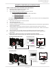
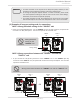
5. Between the “PARENT” and the “CHILD-1” units:
Connect the “PARENT” connector of the “PARENT” unit to the “1” connector of the “CHILD-1” unit
using the supplied linking cable.
6. Between the “CHILD-1” and the “CHILD-2” units:
Connect the “2” connector of the “CHILD-1” unit to the “1” connector of the “CHILD-2” unit.
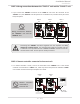
7. Between the “CHILD-2” and the “CHILD-3” units:
Connect the “2” connector of the “CHILD-2” unit to the “1” connector of the “CHILD-3” unit.
8. Verify that all cables are connected like the diagram below (B).
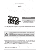
9. Turn on power to the “PARENT” unit. The 7-seg LED will display “1”.
Turn on “CHILD-1”. When the 7-seg LED displays a number, turn on “CHILD-2”.
When the 7-seg LED displays a number, turn on “CHILD-3”.
Make sure the 7-seg LED of all the units' computer boards display the unit #. The numbering system
automatically allocates the unit # to each water heater in the Easy-Link System, in accordance with the
table below.
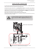
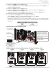
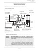
(A) 510 (T-D2) model Computer board
(B) Basic diagram of connections between the Easy-Link System units
NOTE: The dark squares indicate the direction the DIPswitches should be set to.
Type of unit Unit # of easy-link
Parent 1
Child 2, 3 or 4
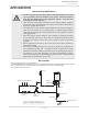
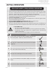
Installaon
Installaon Manual
Communication
cable
Connectors
Right bank of
Dipswitches
OFF
ON
1
2
3
4
5
6
PARENT
1
2
Connectors
Right bank of
Dipswitches
OFF
ON
1
2
3
4
5
6
PARENT
1
2
Connectors
Right bank of
Dipswitches
OFF
ON
1
2
3
4
5
6
PARENT
1
2
Connectors
Right bank of
Dipswitches
OFF
ON
1
2
3
4
5
6
PARENT
1
2
PARENT
unit
CHILD-1
unit
CHILD-2
unit
CHILD-3
unit
Easy-Link System
“Online” LED
Lebankof
DIPswitches
7-Seg. LED
Right bank of
DIPswitches
Easy-Link
connectors are next
to the computer
board.
To change the DIPswitch
settings for the Easy-Link
System, locate the bank of
DIPswitches to the right of
the 7-seg LED.
Do not adjust the left bank
of DIPswitches.