
Manual

Installation
25│Page
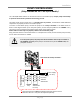
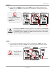
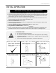
Thedarksquaresindicatethedirectionthedipswitchesshouldbesetto.
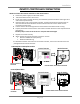
4.Betweenthe“PARENT”andthe“CHILD‐1”units
Connectthe“PARENT”connector ofthe“PARENT”unittothe“[1]”connectorofthe“CHILD‐1”
unit.
5.Betweenthe“CHILD‐1”andthe“CHILD‐2”units
Connectthe“[2]”connec torofthe“CHILD‐1”unittothe“[1]”connectorof the“CHILD‐2”unit.
6.Betweenthe“CHILD‐2”andthe“CHILD‐3”units
Connectthe“[2]”connec torofthe“CHILD‐2”unittothe“[1]”connectorof the“CHILD‐3”unit.
7.Makesurethe7‐seg.LEDofalltheunits’computerboardsdisplaytheunit#.Thenumbering
systemautomaticallyallocatestheunit#toeachwaterheaterintheEasy‐
Linksystem,in
accordancewiththetablebelow.
Parentunit Unit#:1
Childunits Unit#:2,3and4
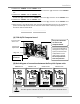
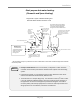
(A)T‐D2‐IN/OSComputerboard
(B)BasicdiagramofconnectionsbetweentheEasy‐LinkSystemunits.
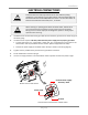
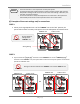
Tochangethedipswitch
settingsfortheEasy‐Link
system,locatethebank
ofdipswitchestothe
rightofthe7‐segLED.
Donotadjusttheleft
bankofdipswitches.
Easy‐Linkconnectors
arenexttothe
com
p
uterboard.
Easy‐Linksystem
“Online”LED
Rightbankof
dipswitches
Leftbankof
dipswitches
7‐Seg.LED
CAUTION
P
A
R
E
N
T
1
2
3
4
5
6
Communication cable
Connectors
Right bank of Dipswitches
OFF
ON
OFF
ON
OFF
ON
OFF
ON
11
11
11
11
22
22
22
22
P
A
R
E
N
T
P
A
R
E
N
T
P
A
R
E
N
T
1
2
3
4
5
6
Right bank of Dipswitches
1
2
3
4
5
6
Right bank of Dipswitches
1
2
3
4
5
6
Right bank of Dipswitches
Connectors Connectors Connectors
PARENTunit CHILD‐1unit
CHILD‐2unit
CHILD‐3unit