TAKAGI On‐Demand Water Heater Installation Manual and Owner’s Guide “ANSI Z21.10.3” and “CSA 4.3” Model ・T‐KJr2‐IN ・T‐KJr2‐OS ・T‐K4‐IN ・T‐K4‐OS ・T‐D2‐IN ・T‐D2‐OS Only T‐D2 models If the information in these instructions is not followed exactly, a fire or explosion WARNING may result causing property damage, personal injury or death. Gas Tankless Water Heater Suitable for potable water heating and space‐heating * *Please refer to local codes for space‐heating compliance.
Contents CONTENTS Installation Manual SPECIFICATIONS…………………………………………………………………………………………..………………………... 3 INTRODUCTION…………………………………………………………………………………………………..…………………. 4 SAFETY GUIDELINES…………….………………………………………………………………………………………..……….. 5 INSTALLATION………………………………………………………………………………………………..…………………..…. 6 General………………………………………………………………………………………………………………………..…..… 6 Clearances…………………………………………………………………………………………………………………………… 8 Included Accessories…………….………………………………………………………………………………………..…..
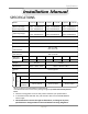
Specifications Installation Manual SPECIFICATIONS Model T‐KJr2‐IN T‐KJr2‐OS T‐K4‐IN T‐K4‐OS T‐D2‐IN T‐D2‐OS Natural Gas Input (Operating Range) Min: 19,500 Btu/h Max: 140,000 Btu/h Min: 11,000 Btu/h Max: 190,000 Btu/h Min: 11,000 Btu/h Max: 199,000 Btu/h Propane Input (Operating Range) Min: 19,500 Btu/h Max: 140,000 Btu/h Min: 11,000 Btu/h Max: 190,000 Btu/h Min: 11,000 Btu/h Max: 199,000 Btu/h Gas Connection ¾” NPT Water Connections ¾” NPT Water Pressure 15 ‐ 150 psi* Natural Gas Inle
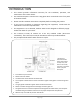
Introduction INTRODUCTION • This manual provides information necessary for the installation, operation, and maintenance of the water heater. • The model description is listed on the rating plate which is attached to the front panel of the water heater. • Please read all installation instructions completely before installing this product. • If you have any problems or questions regarding this equipment, consult with the manufacturer or its local representative.
Safety Guidelines SAFETY GUIDELINES SAFETY DEFINITIONS Indicates an imminently hazardous situation which, if not avoided, will result in death or serious injury. DANGER Indicates an imminently hazardous situation which, if not avoided, could result in death or serious injury. WARNING Indicates an imminently hazardous situation which, if not avoided, could result in minor or moderate injury. CAUTION GENERAL 1. 2. 3. 4. 5.
Installation INSTALLATION GENERAL 1. Follow all local codes, or in the absence of local codes, follow the most recent edition of the National Fuel Gas Code: ANSI Z223.1/NFPA 54 in the USA or CAN/CSA B149.1 Natural Gas, Propane Installation Code in Canada. 2. All gas water heaters require careful and correct installation to ensure safe and efficient operation. This manual must be followed exactly. Read the “Safety Guidelines” section. 3. The manifold gas pressure is preset at the factory.
Installation • Installation and service must be performed by a qualified installer (for example, a licensed plumber or gas fitter), otherwise the warranty will be void. WARNING • The installer (licensed professional) is responsible for the correct installation of the water heater and for compliance with all national, state/provincial, and local codes. • The manufacturer does not recommend installing the water heater in a pit or location where gas and water can accumulate.
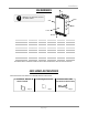
Installation CLEARANCES Top Maintain all clearances around the water heater. Back Side Side Front Bottom Model T‐KJr2‐IN* T‐KJr2‐OS Top 12” 36” Bottom 12” 12” Front 24” 24” Back 1” 1” Sides 2“ 2“ Model T‐K4‐IN* T‐K4‐OS Top 12” 36” Bottom 12” 12” Front 24” 24” Back 1” 1” Sides 2“ 2“ Model Top Bottom Front Back Sides T‐D2‐IN* 12” 12” 24” 1” 2“ T‐D2‐OS 36” 12” 24” 1” 2“ *Standard indoor installations & direct‐vent indoor installations have the same clearances.
Installation OPTIONAL ITEMS Model TK‐RE02 TM‐RE30 TK‐BF01 TK‐TV10 TK‐PC01 TK‐PCJr2 TK‐RB02 TK‐KPWL4 TK‐KPWH4 TK‐KPCT43 T‐KJr2‐IN ✔ T‐KJr2‐OS ✔ ✔ ✔ ✔ T‐K4‐IN ✔ ✔ ✔ ✔ T‐K4‐OS ✔ ✔ ✔ ✔ T‐D2‐IN T‐D2‐OS ✔ ✔ ✔ ✔ ✔ ✔ ✔ ✔ ✔ ✔ ✔ ✔ ✔ 1. Temperature Remote Controller: TK‐RE02 The Temperature Remote Controller has two functions.
Installation 5. Pipe Covers: TK‐PC01 and TK‐PCJr2 6. Recess box: TK‐RB02 The pipe cover protects the The Recess box will allow for plumbing pipes to the water heater “clean” installations. The water from unexpected adjustments. heater fits inside the recess box, This pipe cover is fixed to the which hides and protects the whole water heater and plumbing. bottom of the water heater, which The Recess box will fit in‐between hides the plumbing and improves most wall studs.
Installation HIGH‐ALTITUDE INSTALLATIONS Check the elevation where your water heater is installed. Set dipswitches shown in the table below depending on the altitude. T‐KJr2‐IN/OS & T‐K4‐IN/OS 0 to 2,000 ft (DEFAULT) OFF OFF Altitude Switch No.3 Switch No.
Installation VENTING INSTRUCTIONS ‐General‐ Improper venting of this appliance can result in excessive levels of carbon monoxide which can result in severe personal injury or death. DANGER CAUTION Improper installation can cause nausea or asphyxiation, severe injury or death from carbon monoxide and flue gases poisoning. Improper installation will void product warranty. When installing the vent system, all applicable national and local codes must be followed.
Installation ‐Exhaust venting‐ (For the T‐KJr2‐IN, T‐K4‐IN, & T‐D2‐IN models) This is a Category III appliance and must be vented accordingly. The vent system must be sealed air tight. All seams and joints without gaskets must be sealed with high heat resistant silicone sealant or UL listed aluminum adhesive tape having a minimum temperature rating of 350°F. For best results, a vent system should be as short and straight as possible.
Installation Horizontal Installation Diagram (With direct‐venting) Vertical Installation Diagram (With direct‐venting) Rain Cap Wall Roof Roof Flashing Sidewall Vent Terminator Backflow Preventer * Backflow Preventer * Fire stop Vertical Condensation Drain** Vertical Condensation Drain** See the picture below for detailed connection instructions to the Direct‐Vent Conversion Kit.
Installation ‐Vent termination clearances‐ Canada Direct vent and other than Direct Vent U.S.A Direct vent Other than Direct Vent 1 foot A Clearance above grade, veranda, porch, deck, or balcony. 1 foot 1 foot B Clearance to window or door that may be opened. 3 feet 1 foot 4 feet from below or side opening. 1 foot from above opening.
Installation Please follow all local and national codes in regards to proper termination clearances. In the absence of such codes, the following clearances can be used as guidelines. Local CAUTION codes supersede these guidelines. For sidewall terminations 2ft. 3ft. 1ft. 1ft. 2ft. 1ft. 3ft. 1ft. 3ft. Inside corner Exhaust termination For multiple sidewall exhaust terminations (e.g. multi‐unit systems), an exhaust termination must be at least 1 ft. away from another exhaust termination.
Installation GAS SUPPLY AND GAS PIPE SIZING ‐General‐ • • WARNING • Check that the type of gas matches the rating plate first. Ensure that any and all gas regulators used are operating properly and providing gas pressures within the specified range shown below. Excess gas inlet pressure may cause serious accidents. Conversion of this unit from natural gas to propane or vise versa will void all warranty. Contact your local distributor to get the correct unit for your gas type.
Installation ‐Natural Gas Supply Piping‐ Maximum Delivery Capacity of Cubic Feet of Gas per Hour of IPS Pipe Carrying Natural Gas of 0.60 Specific Gravity Based on Pressure Drop of 0.5” WC Based on Energy Content of 1,000 BTU/Cubic Ft.: The water heater requires 140 Cubic Ft./hr for the T‐KJr2‐IN/OS, 190 Cubic Ft./hr for the T‐K4‐IN/OS, and 199 Cubic Ft./hr for the T‐D2‐IN/OS.
Installation ‐Measuring inlet gas pressure‐ 1. Turn off all electric power to the water heater if service is to be performed. 2. Turn the manual gas valve located on the outside of the unit clockwise 3 to the off position. The water heater cannot perform properly without sufficient inlet gas pressure. Below are instructions on how to check the inlet gas pressure. THIS IS ONLY TO BE DONE BY A LICENSED PROFESSIONAL. 1. Shut off the manual gas valve on the supply gas line. 2.
Installation WATER CONNECTIONS • CAUTION • Do not use this water heater if any part has been submersed under water. Immediately call a licensed professional to inspect the water heater to replace any damaged parts. Do not reverse the hot outlet and cold inlet connections to the water heater. This will not properly activate the water heater. All pipes, pipe fittings, valves and other components, including soldering materials, must be suitable for potable water systems. 1. 2. 3. 4.
Installation ELECTRICAL CONNECTIONS WARNING CAUTION Follow the electrical code requirements of the local authority having jurisdiction. In the absence of such requirements, follow the latest edition of the National Electrical Code ANSI/NFPA 70 in the U.S. or the latest edition of CSA C22.1 Canadian Electrical Code, Part 1, in Canada. When servicing or replacing parts within the water heater, label all wires prior to disconnection to facilitate an easy and error‐free reconnection.
Installation REMOTE CONTROLLER CONNECTIONS 1. 2. 3. Disconnect power supply from the water heater. Take off the water heater’s front cover. Locate the remote controller terminal, pictured below (located around the lower right‐hand side of the computer board). 4. Open the plastic cover of the remote controller, and then attach the two fork terminals to connector base of the backside the remote controller with two screws.
Installation PUMP CONTROL MODE (Only available on the T‐D2‐IN/OS models) The T‐D2‐IN/OS water heaters can be used to control a recirculation pump. Proper pump control helps to preserve the life of the system and saves energy as well. The water heater pump control port is a “normally open dry contact”, and therefore needs additional components to properly control a recirculation pump. To control a recirculation pump, connect the pump to the “Pump” connector in the water heater as shown in the diagram below.
Installation EASY‐LINK SYSTEM (Only available on the T‐D2‐IN/OS models) ‐General‐ The T‐D2‐IN/OS water heaters can be connected with other heaters of the same model with communication cables to work as a multiple‐unit manifold system. • The Easy‐Link system allows up to 4 units to manifold together. • A communication cable (gray color) comes with each T‐D2 model. You can manifold from 2 to 4 units without the need for a multi‐system controller.
Installation 4. Between the “PARENT” and the “CHILD‐1” units Connect the “PARENT” connector of the “PARENT” unit to the “[1]” connector of the “CHILD‐1” unit. 5. Between the “CHILD‐1” and the “CHILD‐2” units Connect the “[2]” connector of the “CHILD‐1” unit to the “[1]” connector of the “CHILD‐2” unit. 6. Between the “CHILD‐2” and the “CHILD‐3” units Connect the “[2]” connector of the “CHILD‐2” unit to the “[1]” connector of the “CHILD‐3” unit. 7. Make sure the 7‐seg.
Installation • NOTICE • • A remote controller is not required for the Easy‐Link system. If running the Easy‐Link system without a remote controller, please make sure the temperature settings on ALL the units are set to the same settings. Otherwise, the units will not operate properly. If a remote controller is used, the temperature on all the units in the system will automatically be set to the same temperature that is set on the remote.
Installation CASE 3: • If you connect the “PARENT” connector of the “CHILD‐1” unit to the “[1]” connector of the “CHILD‐2” unit, the “CHILD‐2” unit will operate as an individual unit, and will not be part of the Easy‐Link system.
Installation APPLICATIONS ‐Space‐Heating Applications‐ • WARNING • • • • • In order to purge air in water pipes within a closed‐loop system, an air vent and air separator should be installed in to the system. Required circulation flow rates are labeled next to each application diagram. These flow rate requirements must be followed.
Installation ‐Dual‐purpose hot water heating‐ (Domestic and Space Heating): Diagramatic Layout of Radiant Heating and Domestic Water Heater Per Mass.
Initial Operation INITIAL OPERATION FOR YOUR SAFETY, READ BEFORE OPERATING • Check the GAS and WATER CONNECTIONS for leaks before firing unit for the first time. • Open the main gas supply valve to the unit using only your hand to avoid any spark. Never use tools. If the knob will not turn by hand, do not try to force it; call a qualified service technician. Forced repair may result in a fire or explosion due to gas leaks.
Operating Safety Ow n er’s Gu id e OPERATING SAFETY FOR YOUR SAFETY READ BEFORE OPERATING WARNING: If you do not follow these instructions exactly, a fire or explosion may result causing property damage, personal injury or loss of life. A. This water heater does not have a pilot. It is equipped with an ignition device that automatically lights the burner. Do not try to light the burner by hand. B. BEFORE OPERATING smell all around the water heater area for evidence of leaking gas.
Operating Safety DANGER Vapors from flammable liquids will explode and catch fire causing death or severe burns. Do not use or store flammable products such as gasoline, solvents or adhesives in the same room or area near the water heater. Keep flammable products: 1. Far away from heater 2. In approved containers 3. Tightly closed 4. Out of children's reach Vapors: 1. Cannot be seen 2. Vapors are heavier than air 3. Go a long way on the floor 4.
Normal Operation NORMAL OPERATION GENERAL WARNING NOTICE • Hot Water temperatures over 125°F (52°C) can cause severe burns instantly or death from scalding. • The outlet hot water temperature of the water heater is factory set at 122°F (50°C). • Feel the water temperature before bathing or showering. • Flow rate to activate the water heater • Flow rate to keep the water heater running 1. Open a hot water tap.* : 0.75 gallon per minute : 0.4 gallon per minute 2.
Normal Operation ‐Dipswitch settings for each temperature on the computer board‐ Temperature Settings 113 F ON (45 C) OFF 1 2 3 4 5 6 7 8 122 F (50 C) DEFAULT ON 1 2 3 4 5 6 7 8 OFF 131 F ON (55 C) OFF 1 2 3 4 5 6 7 8 140 F ON (60 C) OFF 1 2 3 4 5 6 7 8 Temperature Settings 104 F ON (40 C) OFF 140 F ON (60 C) OFF 1 2 3 4 5 6 1 2 3 4 5 6 113 F ON (45 C) OFF 158 F ON (70 C) OFF 1 2 3 4 5 6 122 F (50 C)
Normal Operation FLOW • The flow rate through the water heater is limited to a Household Flow Rates maximum of 6.6 GPM for the T‐KJr2‐IN/OS, 8.0 GPM for Appliance / Use Flow Rate (GPM) the T‐K4‐IN/OS, and 10.0 GPM for the T‐D2‐IN/OS. Lavatory Faucet 1.0 • The temperature setting, along with the supply Bath Tub 4.0 – 10.0 temperature of the water will determine the flow rate Shower 2.0 output of the unit. Kitchen Sink 1.5 • Please refer to the temperature vs. gallons per minute Dishwasher 1.5 chart on p.
Normal Operation MAINTENANCE AND SERVICE WARNING Turn off the electrical power supply and close the manual gas shutoff valve and the manual water control valve before servicing. • • • • • Clean the cold‐water inlet filter. (Refer to diagram below) Be sure that all openings for combustion and ventilation air are not blocked. The venting system should be checked annually for any leaks, corrosion, blockages or damage. The burner should be checked annually for dust, lint, grease or dirt.
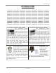
Troubleshooting TROUBLESHOOTING GENERAL PROBLEM It takes long time to get hot water at the fixtures. SOLUTIONS • The time it takes to deliver hot water from the water heater to your fixtures depends on the length of piping between the two. The longer the distance or the bigger the pipes, the longer it will take to get hot water. • If you would like to receive hot water to your fixtures quicker, you may want to consider a hot water recirculation system. (p.
Troubleshooting ‐EASY‐LINK SYSTEM‐ (Only T‐D2‐IN/OS models) ‐TM‐RE30/TK‐RE02 (OPTIONAL)‐ ‐ WATER HEATER ‐ PROBLEM Unit does not ignite when water goes through the unit. SOLUTIONS • Is the flow rate over 0.75 GPM? (p. 33) • Check for the filter on cold water inlet. (p. 36) • Check for reverse connection and cross connection. • If you use the remote controller, is the power button turned on? • Check if the inlet temperature is too high. The fan motor is still spinning after operation has stopped.
Troubleshooting ERROR CODES • • • The units are self diagnostic for safety and convenience when trouble shooting. If there is a problem with the installation or the unit, depending on the model or if there is a remote controller installed, it will either display a numerical error code on the 7‐Seg LED on the computer board (Only for the T‐D2‐IN/OS models), display a blinking red LED (for the T‐KJr2‐IN/OS & T‐K4‐IN/OS models), or the error code will display on the remote controller if it is installed.
Troubleshooting ‐FAULT ANALYSIS OF ERROR CODES‐ If the error code displayed on the computer board of the Water heater or remote controller, please check the following. After checking, Consult with the manufacturer.
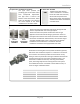
Troubleshooting T‐KJr2‐IN/OS & T‐K4‐IN/OS T‐D2‐ IN/OS Red LED RE02 RE30 N/A N/A 441 Six Times 51 510 Six Times 55 N/A Abnormal Main Gas Valve • Check for connection/breakage of wires (Part #708) and/or burn marks on the computer board (Part #701). Four Times 61 611 Fan Motor Fault • Check for connection/breakage of wires, dust buildup in the fan motor (Part #103) and/or burn marks on the computer board (Part #701). • Check for frozen/corrosion of connectors (Part #103).
Components Diagram COMPONENTS DIAGRAM Case assembly T‐KJr2‐IN T‐KJr2‐OS 003 052 052 052 004 004 007 007 052 053 001 702 702 052 052 002 704 001 002 704 006 051 006 066 066 053 053 056 056 005 005 050 052 050 052 T‐K4‐OS & T‐D2‐OS T‐K4‐IN & T‐D2‐IN 003 052 052 052 004 004 007 007 001 001 053 052 702 702 052 052 002 051 704 002 704 006 006 066 066 053 053 056 056 005 005 050 052 050 052 42│Page
Components Diagram Burner assembly T‐KJr2‐IN/OS Burner assembly 101 107 110 106 105 108 065 104 709 109 111 401 712 059 053 052 706 053 121 703 053 059 704 112 705 103 053 113 114 150 708 701 Manifold assembly 053 058 713 115 102 Only T-KJr2-IN 061 053 067 119 120 151 053 055 711 062 118 712 714 055 053 43│Page 052
Components Diagram T‐K4‐IN/OS & T‐D2‐IN/OS Burner assembly 101 107 106 105 108 065 104 709 109 110 111 401 712 053 T-K4-IN T-K4-OS Power control section 121 706 053 703 A 053 052 116 704 117 705 053 T-D2-IN T-D2-OS 053 103 121 054 112 706 703 A 053 704 115 113 705 057 114 058 053 150 701 708 A Manifold assembly 053 T-K4-IN T-D2-IN 713 Fan motor section for IN models 102 061 053 067 119 053 712 151 T-D2-IN T-D2-OS 120 055 062 066 062 118 059 060 053 711 053
Components Diagram Computer board Assembly T‐KJr2‐IN/OS & T‐K4‐IN/OS 710 T‐D2‐IN/OS 701 103 708 701 707 717 103 707 718 710 709 402 402 708 716 714 715 709 719 408 407 719 Water way assembly T‐D2‐IN/OS T‐K4‐IN/OS T‐KJr2‐IN/OS 463 463 463 453 413 453 413 453 413 452 450 452 452 414 450 450 414 414 412 412 412 063 063 063 401 401 401 B 451 414 454 C 414 411 459 414 403 B B 462 Bypass section 458 C C 460 451 451 456 C 153 154 456 460 460 456 4
Output Temperature Chart PARTS LIST Item# Description Part# Item# Description Part# 001 Case assembly for T‐KJr2‐IN for T‐KJr2‐OS for T‐K4‐IN & T‐D2‐IN for T‐K4‐OS & T‐D2‐OS EK415 EK432 EK402 EKK41 101 Burner assembly for T‐KJr2‐IN/OS Burner assembly for T‐K4‐IN/OS & T‐D2‐IN/OS EK417 EKH5W 002 Front cover for T‐KJr2‐IN for T‐KJr2‐OS for T‐K4‐IN for T‐K4‐OS for T‐D2‐IN for T‐D2‐OS Air blockage plate for T‐KJr2‐IN, T‐K4‐IN & T‐D2‐IN Bracket Junction box Junction box inner plate EK419 EK433 EK40
Output Temperature Chart Item# Description Part# Item# Description Part# 118 119 120 121 Gas inlet Gas inlet ring Igniter plate Surge box plate for T‐KJr2‐ IN/OS & T‐K4‐IN/OS Surge box plate for T‐D2‐IN/OS EKK1E EKK2Z EKK1B EKK4H 412 EM212 413 414 415 Hi‐Limit switch for T‐KJr2‐ IN/OS & T‐K4‐IN/OS Hi‐Limit switch for T‐D2‐IN/OS Overheat‐cut‐off fuse Heater Inlet heater O‐ring P18 NBR (Black) O‐ring P20 NBR (Black) Silicon ring for T‐KJr2‐OS Silicon ring for T‐K4‐OS & T‐D2‐OS Rain protection pla
Output Temperature Chart Item# Description Part# Item# Description Part# 710 EH‐IG wire for T‐KJr2‐IN & T‐K4‐IN EKK3R EH‐IG wire with freeze protection thermostat for T‐KJr2‐OS, T‐K4‐OS & T‐D2‐OS EKK40 715 716 717 718 Pump and multi cable for T‐D2‐IN/OS Thermistors wire for T‐D2‐IN/OS RS‐VG wire for T‐D2‐IN/OS Water valves wire for T‐D2‐IN/OS EKK36 EKK1Z EKK35 EKK33 EH‐IG wire for T‐D2‐IN Igniter High voltage igniter cable Freeze protection thermostat for T‐KJr2‐IN, T‐K4‐IN & T‐D2‐IN Proporti
Output Temperature Chart Output Temperature vs. GPM (Max. 8.0 GPM) with Various Inlet Water Temperature Out Put Hot Water GPM 10.0 40 F 8.0 50 F 60 F 70 F 6.0 4.0 2.0 0.0 100 105 110 115 120 125 130 135 140 150 160 165 40 F 5.2 4.8 4.4 4.1 3.9 3.7 3.5 3.3 3.1 2.8 2.6 2.5 50 F 6.2 5.7 5.2 4.8 4.4 4.1 3.9 3.7 3.5 3.1 2.8 2.7 60 F 7.8 6.9 6.2 5.7 5.2 4.8 4.4 4.1 3.9 3.5 3.1 3.0 70 F 8.0 8.0 7.8 6.9 6.2 5.7 5.2 4.8 4.4 3.9 3.
Warranty PRODUCT REGISTRATION AND LIMITED WARRANTY 1. Product registration card or form: The enclosed product registration card must be completed and returned within 45 days of original purchasing date by retail buyer. Copy of proof of original purchasing date must be sent in with the registration card. The customer may register online with attached proof of original purchasing date via the Internet (www.takagi.com). THE CARD OR FORM IS FOR PRODUCT REGISTRATION.
Warranty (1) Heat exchanger (2) An on‐demand recirculation system is a system that utilizes either a push‐button or other type of manual activation (as opposed to automatic activation with a temperature sensor or timer) to activate the circulation pump. An on‐demand recirculation system can use either the existing cold water line as the return line or have its own dedicated return line.
• Introduction of untreated or poorly treated well water into the product. • Introduction of water with pH levels less than 6.5 and greater than 8.5 into the product.