
User's Manual
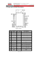


Table Of Contents

A2.1 - 4 of 7
16 GND P GND
17 SWDCLK I JTACK Clock
18 SWDIO I/O JTACK Data
19 DTM_Mode I
Set Low to DTM Mode
Set High to BLE Mode
20 NC NC Not Connect
21 BLE_RX I UART RX
22 BLE_TX O UART TX
23 BLE_CTS O UART CTS
24 BLE_RTS I UART RTS
25 NC NC Not Connect
26 Paring_Key I Set Low to Paring Device
27 NC NC Not Connect
28 LED O LED indicator
29 GND P GND
30 NC NC Not Connect
Note.1 DTM is Direct Test Mode。
2. Power supply
The Module accept 3.1V to 4.2V DC voltage input,Power supply should
guarantee good ripple suppression and enough current.
3. Antenna
The module integrates a chip antenna so there’s no need to use antenna on
customer’s PCB.
4. UART interface
This is a standard UART interface for communicating with other serial devices.
The UART interface provides a simple mechanism for communicating with
other serial devices using the RS232 protocol.
The UART CTS and RTS signals can be used to implement RS232 hardware
flow control where both are active low indicators.
Default parameter set is 19200,8,n,1