
User's Manual
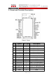


Table Of Contents

A2.1 - 3 of 7
1. Pinout and Terminal Description
Figure 1: Pinout
Pin
Symbol
I/O Type
Description
1 BAT_Monitor I Battery Voltage Monitor
2 VBAT P Power input
3 VBAT P Power input
4 VCC P Power Output
5 VCC P Power Output
6 VCC P Power Output
7 NC NC Not Connect
8 DEV_STAT O Wakeup Device
9 PIO-0 I/O GPIO
10 PIO-1 I/O GPIO
11 DTM_RTS I UART RTS signal (Note.1)
12 DTM_CTS O UART CTS signal (Note.1)
13 DTM_TX O UART TX signal (Note.1)
14 DTM_RX I UART RX signal (Note. 1)
15 GND P GND