
User Manual


42/68 Revision 2.1 December 2009
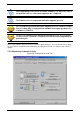
This tab is used either:
• To check / update pedestal clock.
• To check / toggle GPIOs Level.
• To check antenna noise level.
• To check / configure people counter.
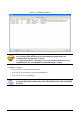
• To check alarms database.
Checking / Updating pedestal clock
Pedestal clock is displayed in real-time in the “Date & Time” section. Click “Synchronize Time” to
synchronize pedestal clock with computer clock.
Checking GPIO level
The two GPIO available to user can be monitored:
Display shows “High” when voltage level is above 2 Volt.
Display shows “Low” when voltage level is below 1 Volt.
See Table 3 for more detailed information.
Clicking with the mouse on GPIO text field, the Level value toggles between High & Low.
The effect will depend on the actual GPIO settings on Basic Configuration Tab.
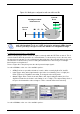
Checking antenna noise level
In “Antenna Noise Level” section, bar graphs provide a feedback regarding the ambient noise level
measured by each antenna. It is only provided as debug purpose and should not be seen as a
measure of performance. Green shows standard conditions as opposed to orange and red displays
warning of possible/likely performance reduction due to ambient noise level.
Checking / configuring people counter
The “People Counter” section displays the total number of people that crossed the IR sensor:
• Whatever the direction (In & Out) if no bidirectional IR sensor is installed.
• In each direction (In & Out) if bidirectional IR sensor is installed.
An icon briefly appears in real-time in “People Counter” section as the sensor IR beam is crossed.
Pedestal clock is used as a date stamp when a theft is committed.
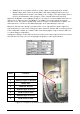
GPIO #1 can be set as an Input Trigger for RF powering off/on as well as
an Output for driving an External Alarm Device
GPIO #2 can only be used as an Output for driving an External Alarm
Device
People counter value is battery backed-up, and is consequently restored
at power-up.