
User Manual


32/68 Revision 2.1 December 2009
L-SP3 Master and all others pedestals set as Slaves. Each pedestal is connected to the other
using ideally a twisted pair cable. This cable will propagate the synchronization signal to all
pedestals in parallel.
Wire connection:
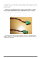
First prepare a cable of appropriate length to connect 2 consecutive Electronics as shown in
Figure 14 and Figure 15. A minimum wire gauge of 22AWG (0.2mm²) is enough, preferably a
twisted pair. Screw at each extremity of the cable a 2-way connector with ground wire at the same
position for each module. If more than 2 pedestals are used to form the aisle, then connect the
wires in parallel to go to the next pedestal until you reach the last one.
Figure 14: Detailed of Wire Synchronization Assembly
Then unscrew the 4 screws to open the bottom plastic cover panel of each pedestal forming
the aisle to gain access to the Product Electronic Module and connect the top 2-way connector as
shown in Figure 15 thereafter.