
User Manual


December 2009 Revision 2.1 27/68
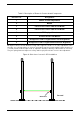
3. Remove the pedestal from the box.
4. Remove the plastic cover from the both sides after removing the 4 fixing screws.
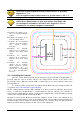
5. Engage the power supply cable in the electric sheath and the Ethernet cable in the other
sheath (please refer to section 4.1.1 “Wire Feed Sheaths”).
6. Place the pedestal base over the mounting holes. Insert and fasten the screws in the mounting
holes according to the type of ground surface:
Wooden floor: Insert the screws directly into the mounting holes and tighten the screws in
place.
Concrete floor: Insert the screws into the concrete floor plugs and tighten the screws in
place.
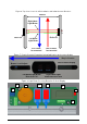
7. Plug in the mains IEC power cord from the previous pedestal if daisy chained or from the wall
mounted socket. See figure in Chapter Electrical Safety Rules
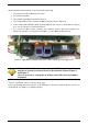
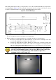
8. Once all the L-SP3 pedestal have been installed, close the micro circuit-breaker (Figure 3) to
power up the system before starting configuration operations. Please see section 5
“Configuration”.
9. After the configuration has been carried on, replace the two plastic covers and tighten the 4
fixing screws.
When tightening the screws in place, first tighten the screws in place ¾
of the way. Once all screws are in place, then tighten each screw
progressively, one after each other to ensure that the floor bracket is
solidly fixed into place and completely vertically aligned. The use of a
level may be required.
No Live AC mains 110/230V during installation!
Make sure there is no power supply current before carrying on the
connection operations.
To do so, unplug the IEC Power Cord from the wall socket.