
User Manual


December 2009 Revision 2.1 25/68
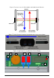
Table 2: Description of Buzzer & Counter board Components
Reference n° Designation
1 Buzzer Volume Adjustment
2 Buzzer
3 Photoelectric Reflex Switch Red Beam
4 Photoelectric Reflex Switch Red Beam
5 LCD Display & Counter
6 Counter Reset Push Button
7 Hexagonal Screw for Light Beam Vertical Alignment
8 Hexagonal Screw for Light Beam Horizontal Alignment
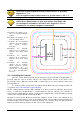
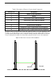
On Figure 8 above, the two Beam Crossing Cells support is shown. To do a fine adjustment of the
2 beams, use a hexagonal key to screw or unscrew the top left screw (to adjust height of beams ref
7 circled) and the bottom right screw (to adjust the lateral positioning of the beams ref 8 circled).
They are spring loaded to improve accuracy and keep in place the two sensors after adjustment.
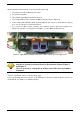
Figure 9: Side view of correct L-SP3 installation
Ground
Reflector