
User's Manual

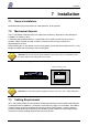


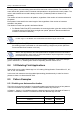

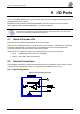
Table Of Contents

Installation
7 Installation
7.1 General Installation
Read/antenna/ILS layout and maximum cable distances, to be specified.
7.2 Mechanical Aspects
The L-L100 Reader is delivered with four rubber pads screwed on the bottom of the package for
installation on a table or desk.
A mounting plate available with the L-L100 Reader can be used to mount the unit in various
positions. When mounted vertically, the BNC connectors must be facing upwards and
perpendicular to the floor.
When installing the L-L100 Reader on the mounting plate, remove the rubber pads from the L-L100
Reader and fasten the unit directly to the mounting plate.
CAUTION: The screws must be always attached to the bottom of the L-L100 Reader even if
the rubber pads and mounting plate are not used.
Figure 6: Authorized Installation Positions
BNC Connectors on Top
CAUTION: For continuous protection against risk of fire, use only T 2.5A – 250V rated fuses.
7.3 Cabling Requirements
All L-L100 Reader cables must be shielded. Shielding effectiveness of the material used should be
of Good performance (60dB min.), especially in the frequency range of 10 to 60 MHz. The addition
of ferrite clamps near the input/output will increase common mode rejection. TAGSYS antenna
products are delivered with good performance shielded coaxial cables with ferrite beads already
mounted to increase shielding effectiveness at low frequencies.
April 2003 Revision 3.1b 23/45