LIBRARY SECURITY PEDESTAL 2 End User's Guide Revision 1.
LIBRARY SECURITY PEDESTAL 2 Publishing Information Disclaimer and Limitation of Liability All information herein is either public information or is the property of and owned solely by TAGSYS who shall have and keep the sole right to file patent applications or any other kind of intellectual property protection in connection with such information.
Read This First Read This First Welcome to the TAGSYS L-SP2 Article Surveillance (EAS) system. This user’s guide is designed to help you get up and running quickly using this high-quality Radio Frequency Identification (RFID) Anti-Theft system. It describes all you need to know about how to install and use the TAGSYS EAS system and its associated applications.
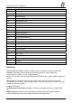
LIBRARY SECURITY PEDESTAL 2 ETX End of Text HPI Host Port Interface I/O Input/Output IFD Interface Device LED Light Emitting Diode LSb Least Significant Bit LSB Least Significant Byte MSb Most Significant Bit MSB Most Significant Byte OS Operating System PC Personal Computer PCB Printed Circuit Board RAM Random Access Memory RF Radio Frequency RFID Radio Frequency Identification RFU Reserved for Future Use RPU Radio Processing Unit RTC Real Time Clock SAM Security Acces
Read This First Dynamic-Link Library Executable routines that are stored as separate files with DLL extensions and executed only when needed by the program. Host Port Interface Interface used to access the DSP memory. IEC Connector Three-pin connector used on sockets that carry mains electricity to the computer. All PCs use a male IEC connector and mains lead with a female IEC connector. Interrogation Pulse A signal transmitted by the coupler to activate the TAGSYS RFID tag’s transponder.
LIBRARY SECURITY PEDESTAL 2 If you need assistance Please contact your nearest TAGSYS sales representative or the TAGSYS welcome desk at: Telephone Fax: E-Mail: +33 (0) 4 91 27 57 00 +33 (0) 4 91 27 57 01 info@tagsys.net Website: http://www.tagsys.net/ Contact for Comments We welcome your feedback to help us provide high quality documentation. For technical comments, please contact our welcome desk: Telephone: Fax: E-Mail: +33 (0) 4 91 27 57 00 +33 (0) 4 91 27 57 01 info@tagsys.
Read This First Table of Contents Publishing Information________________________________________________________________ 2 Disclaimer and Limitation of Liability_________________________________________________________ 2 Read This First _______________________________________________________________________ 3 Conventions _______________________________________________________________________________ 3 Abbreviations and Acronyms ________________________________________________________________ 3 Glossary __
LIBRARY SECURITY PEDESTAL 2 6 Antenna Tuning _________________________________________________________________ 33 6.1 Required Materials___________________________________________________________________ 6.1.1 TAGSYS Antenna Tuning Kit (not included) __________________________________________ 6.1.2 Oscilloscope _____________________________________________________________________ 6.1.3 Probes __________________________________________________________________________ 6.
For Your Safety 1 For Your Safety 1.1 General Use The L-SP2 is designed to be rugged and reliable and to provide years of trouble-free service. Please observe the following general tips: Take care not to scratch the device. Keep the device clean. When working with the device, use only TAGSYS-approved accessories. This device is not waterproof and should not be exposed to rain or moisture. Under extreme conditions, water may enter the circuitry. Protect the device from extreme temperatures.
LIBRARY SECURITY PEDESTAL 2 1.3 Important Safety Information 1.3.1 Operating Environment When connecting the device or any accessory to another device, read its user’s guide for detailed safety instructions. Do not connect incompatible products. As with all RF equipment, users are advised that the equipment should only be used in its normal operating position. 10/50 Revision 1.
Certification 2 Certification 2.1 Occupational Health TAGSYS L-SP2 EAS System has been designed and tested to be in conformity with the European Standard EN 50364 “Limitation of human exposure to electromagnetic fields from devices used in Electronic Article Surveillance (EAS), Radio Frequency Identification (RFID) and similar applications” in conjunction with the European Standard EN 50357 describing how to evaluate the exposure level. 2.1.
LIBRARY SECURITY PEDESTAL 2 2.3 Regulatory Notices An RFID system typically composed of an RF emission device such as the L-SP2 connected to an antenna is subject to national regulations that may differ by country. One important item to consider is the maximum permissible magnetic field intensity at a distance of 10 meters from the antenna that must not exceed 42 dBµA/m in Europe and 38 dBµA/m in US. The L-SP2 meets these limits. 2.3.
Certification 2.3.2 In USA (FCC Directive) L-SP2 WARNING TO USERS IN THE UNITED STATES FEDERAL COMMUNICATIONS COMMISSION (FCC) RADIO INTERFERENCE STATEMENT 47 CFR Section 15.105(b) This equipment has been tested and found to comply with the limits for a Class B digital device, pursuant to Part 15 of the FCC Rules. These limits are designed to provide reasonable protection against harmful interference in a residential installation.
LIBRARY SECURITY PEDESTAL 2 3 System Overview 3.1 Features Being a standalone solution, TAGSYS Security Gates do not need to be linked to the library database, and can still operate when the Integrated Library System (ILS) is down or under maintenance. The security gate does not require additional equipment to operate.
Installation 4 Installation 4.1 L-SP2 EAS System Components The components included in the L-SP2 EAS System package are listed in Table 1. The entire kit is delivered in a box as shown in Figure 1. Table 1: L-SP2 EAS System Components Quantity Description 1 L-SP2 Pedestal 8 40 mm Philips-head, countersunk screws with a diameter of 6 mm 8 8 mm plastic cement plugs 1 L-SP2 EAS System CD-ROM 1 RS 232 cable Figure 1: Delivery of L-SP2 EAS System Components 4.
LIBRARY SECURITY PEDESTAL 2 4.2.2 Placement of Pedestals CAUTION: In the case of several pedestal row installation then it is significant that all L-SP2 being positioned in the same direction (the people counter of each looking forward the same direction) Pedestals must be mounted between 800 and 915 mm apart (center to center) for maximum reliable performance. There should be at least one pair of pedestals at each entrance/exit point of the library.
Installation 3. Remove the pedestal from the box. 4. Place the cover face to you with the display counter on the other side then remove the 4 screws from the bottom cover. Figure 3: L-SP2 Bottom The 4 screws 5. Remove the plastic cover and then un-clip the metallic cover of the electronics box. Then pull out the opposed cover which will come together with the opposite metallic cover. Figure 4: Open Pedestal Bottom Cable access hole Ac main PCB 6.
LIBRARY SECURITY PEDESTAL 2 7. Insert the power supply cable into the Electronics Unit through the cable access hole as shown above. Check that the cable is correctly positioned and that there are no friction points. 8. Insert and fasten the screws in the mounting holes according to the type of ground surface: a. Wood floor: Insert the screws directly into the mounting holes and tighten the screws in place. b. Concrete floor: Insert the screws into the concrete floor plugs and tighten the screws in place.
Installation Clip 10. At this stage, the L-SP2 must be configured before reassembling the bottom pedestal. To carry on configuration operations (Please see section 5,”Configuration«). We recommend you to install the whole pedestals before carry on configuration operations 11. Power up the system before starting configuration. 12. Once the configuration has been carried on, the L-SP2 can be reassemble following steps 4 and 5 in reverse order. December 2004 Revision 1.
LIBRARY SECURITY PEDESTAL 2 5 Configuration All configuration operations of L-SP2 systems are carried on with the L-SP2 Configuration Utility. 5.1 Understanding the L-SP2 Synchronization Process To determine the status of each EAS anti-theft bit, each pedestal generates a short but substantial radio frequency burst whose energy can interfere with other nearby EAS pedestals.
Configuration Figure 8: Configuration Sample (1 Master/ 4 Slaves) T Synchronization burst MASTER Pt SLAVE1 SLAVE2 SLAVE 3 SLAVE 4 In this case it is recommended to put the Master in the middle of the Slaves for a better propagation and detection of the synchronization burst. Table below describes the maximum Slaves pedestals number depending on chips types to be detected.
LIBRARY SECURITY PEDESTAL 2 5.2 Using the Configuration Software Don’t forget to power up your installation before carrying on the following steps Connect your PC RS232 COM port to the L-SP2 as shown below. Figure 9: PC Connection to Pedestal RS232 cable connected to the PC COM port 5.2.1 Installing the Configuration Software The L-SP2 Configuration Utility is on the CD-Rom provided with the L-SP2. Launching the Installer from the CD-Rom will display the following window: 22/50 Revision 1.
Configuration Follow the installer steps: After the L-SP2 Configuration Software is installed, a shortcut to the application will be added to the desktop and to the Start Menu. December 2004 Revision 1.
LIBRARY SECURITY PEDESTAL 2 5.3 Configuration of the L-SP2 Before you configure the whole L-SP2, you need to have a clear vision of which systems will be the Masters or the Slaves. (Refer to section 5.1,”Understand the EAS Pedestals Synchronization Process “) CAUTION: In a configuration case with several pedestals, as pedestal are default Master configured, they will mutually perturb when powered on. So the first step will be to set the Slaves pedestals chosen as Slave. 5.3.
Configuration Figure 11: Example of Configuration Once the communication is set and the system identified, the software displays the current configuration recorded in the L-SP2. Reset Com Reset the communication to the gate regarding Com Mode, Com Port and IP/Port settings. Release Com Release the communication to the gate. (Get back to Figure 10 ) Chips Select the chips to be decoded More chips you select less pedestal can be synchronized.
LIBRARY SECURITY PEDESTAL 2 Memory Reading When selected, the L-SP2 will try to read memory of items (with EAS activated) passing through the gate. Synchro Select whether the pedestal is to be configured as the Master or as the Slave (1, 2, …7) Only one Master can be selected with several slaves.
Configuration Suspend EAS Click the button to stop EAS detection. Another click resumes EAS detection. Once you have set the basic configuration check that all the slaves are well synchronized. To do so, L-SP2 electronics unit green LEDs should flicker cyclically. If not, proceed to the advanced configuration stage. Database Each time an item (with EAS activated) passes through the gates an entry is added to a local database in L-SP2 memory.
LIBRARY SECURITY PEDESTAL 2 Click: “Refresh” to re-download Database. “Clear” to ERASE L-SP2 Database. “Close” to close the window. You can access the database from your own application using MedioSTX.dll. Please refer to the Medio STX Windows DLL Programming Guide. Date & Time The top of this section continuously displays date and time of the gate. Click “Synchronize Time” to synchronize the gate to the PC clock. Be advised that this time will be used as a date stamp when a theft is committed. 5.3.
Configuration - The master antenna is transmitting the synchronization pattern - The slave antenna is receiving the synchronization pattern - The level sensitivity of the slave receiving antenna According to the number of L-SP2 installed in close proximity the following rules will apply: • The slave pedestal is directly facing the master The slave antenna receiving the synchronization pattern is defined to be at a different position regarding the master-transmitting antenna.
LIBRARY SECURITY PEDESTAL 2 Figure 16: Slave Pedestal not Directly Face to the Master Transmitting Antenna Receiving Antenna • Detection level If recommendations given before do not permit to ensure the synchronization of all Slaves, it is possible to adjust the sensibility of non-synchronized Slaves. You just have to adjust the detection level until you get the required synchronization (LEDs flicking cyclically). Range detection level is between 50 to 1000.
Configuration Motion Detector • Status: Display if a motion detector is present • Alarm: 2 possibilities 1. Set alarm to raise even if no motion is detected 2. Set alarm to raise only if motion is detected. 5.4 Alarm Buzzer Volume Adjustment The alarm buzzer is located at the top of the pedestal. To access to the buzzer potentiometer unscrew the two screws on each side and remove the top cover as shown in the following figures.
LIBRARY SECURITY PEDESTAL 2 5.5 People Counter Reset To reset the people counter use a pointed element (for example: a paper clip) and insert it in the hole under the display window and press (not to strong) until you get zero displayed. Figure 20: People Counter Counter window Hole 32/50 Revision 1.
Antenna Tuning 6 Antenna Tuning The successful operation of the L-SP2 depends largely on: the antenna being tuned to the correct resonance frequency (impedance), antenna isolation being adjusted to its optimal value. During on-site tuning, antennas are decoupled to ensure that the minimum amount of energy is delivered from one antenna to another. Note that antennas are tuned before shipping and should not require any further adjustments on site.
LIBRARY SECURITY PEDESTAL 2 - 100 MHz analog bandwidth (-3 dB) - 5mV/division vertical resolution - 10ns/div horizontal timebase resolution The measurements are taken on the sinewave and repetitive carrier signal, so when using a digital scope, the sampling rate should be at least twice the maximum analog bandwidth. 6.1.3 Probes At least one standard probe (not supplied with the TAGSYS Antenna Tuning Kit) will be required for measuring a trigger signal for the normal tests.
Antenna Tuning Figure 21: Antenna Tuning (Impedance) L-SP2 Figure 22:Antenna Connection Antenna 1 Antenna 2 Antenna 3 Table 4: Oscilloscope Settings Parameter Value “Measure” Channel Sensitivity 1 V/Div. “Reference” Channel Sensitivity 2 V/Div. Time Base 20 ns/Div. The antennas should be tuned in the following order: top, center and then bottom. For the best impedance, adjust the trimmer capacitors (Figure 23) until the two curves on the oscilloscope are exactly superimposed.
LIBRARY SECURITY PEDESTAL 2 Figure 23: Trimmer Capacitor Figure 24: Adjusting Trimmer Capacitors The individual impedance for each antenna should be tuned to be as close as possible to: Z0 = 50±5 + 0j±5 Ω at 13.560 MHz Figure 25: Impedance Values using the Tuning Kit Poor Impedance Good Impedance Continue the tuning process by checking the antenna isolation (see section 6.4, Adjusting the Antenna Isolation) 6.3.
Antenna Tuning Figure 26: Antenna Tuning (Impedance) using an Impedance Analyzer EAS Pedestal Network Impedance Analyzer RF Out R A Top Antenna B Center Antenna Transmission/Reflexion Set Bottom Antenna RG-58 Cables Calibration Plane (50 Ohms + 0j) Adjust the trimmer capacitor (Figure 24) of each antenna for best impedance until the impedance reaches 50±5 + 0j±5 Ω at 13.560 MHz. Continue the tuning process by checking the antenna isolation (see section 6.4, “Adjusting the Antenna Isolation”).
LIBRARY SECURITY PEDESTAL 2 sine wave carrier generator. Poor isolation is approximately –10 dB or 2 Vpp residual peak-to-peak voltages. Optimum isolation is obtained by sliding carefully the top or bottom antenna towards the fixed and center antenna. When a minimum value is reached, the antenna position can be secured using the 4 screws. The voltage is measured using an oscilloscope of at least 100-MHz analog bandwidth, 10-ns time resolution and a 50-Ohm cable terminated at the oscilloscope input. 6.4.
Antenna Tuning Figure 29:Antenna Adjustment Screw Adjustment screw The center antenna always remains fixed in position and connected to the antenna-tuning device. The other two antennas should be slightly loosened so they can be moved with relative ease but do not move on their own (Figure 29) The isolation should be checked as follows: 1. Adjust the position of the bottom antenna with respect to the center antenna. 2.
LIBRARY SECURITY PEDESTAL 2 Figure 30: Antenna Tuning (Isolation) with Impedance Analyzer EAS Pedestal Network Impedance Analyzer RF Out R A Top Antenna B Center Antenna Transmission/Reflexion Set Bottom Antenna Calibration Plane (50 Ohms + 0j) RG-58 Cables Figure 31: Isolation Values using an Impedance Analyzer Poor Isolation Good Isolation Note that the isolation adjustment process often requires repeating the procedure several times between the top and center antennas and between the center an
Operation 7 Operation 7.1 Theory of Operation The RF motherboard in the electronics unit produces radio frequency (RF) electromagnetic signals that are transmitted via the antennas in each pedestal. Each antenna transmits for a short period, receives for a short period, and is inactive for the remainder of the time. When a TAGSYS RFID tag enters the electromagnetic field between two pedestals, some of the RF energy (AC) is converted to DC energy and used to power the TAGSYS RFID tag’s microchip.
LIBRARY SECURITY PEDESTAL 2 8 Maintenance 8.1 Servicing the Pedestals No regular servicing or maintenance is required, except for keeping the covers clean, and occasionally checking the integrity of the cover seals. It is recommended that the pedestal unit be inspected at least once per year by an approved TAGSYS technical representative. Refer to Section 1.2, ”Care and Maintenance” for general maintenance information. 8.
Troubleshooting 9 Troubleshooting The following table lists the most common problems and describes their solutions. Table 6: Troubleshooting Table Fault No power. Possible Causes Cabling fault. Power cable fault System fuse Alarms missed (TAGSYS RFID tags with theft bit ON not triggering Tuning fault. alarms). False alarms (TAGSYS RFID tags Tuning fault. with theft bit OFF trigger alarms). Nearby devices are interfering with the pedestals. (Refer also to section 9.
LIBRARY SECURITY PEDESTAL 2 10 Technical Specifications 10.1 Mechanical Data Parameter Weight Pedestal dimensions (H x W x D) Connection for pedestal Value Pedestal: 34 kg (75 lb) Approx. 1777 mm x 640 mm x 80 mm (70 x 25.2 x 3.15 in) assembled Supply power cable 10.2 Electrical Data Parameter Power supply Power consumption Conformity Microchip compatibility Operating temperature Storage temperature Fuse Value 100/240 Volts AC, 0.
Technical Specifications Figure 32: Mechanical Dimensions of Pedestal Base F Figure 33: Mechanical Dimensions of Pedestal Base December 2004 Revision 1.
LIBRARY SECURITY PEDESTAL 2 11 Performance Test 11.1 Test Conditions Distance between each pedestal not greater than the maximum recommended distance of 915 mm (3 ft.). All tags used must have the theft bit set. Use of reference tag (Antenna Tuning Kit Test Card) is strongly recommended for repeatable results. Testing to be carried out at walking pace (maximum of 1 meter/second). Metal, conductive materials, human hands or body must not shield tags.
Performance Test L-SP2 EAS Performance Test Library / Facility installed: ______________________________ Location of Pedestals: ______________________________ Specific installation notes: ______________________________ Figure 36: Test Chart Pedestal A Pedestal B S/N: S/N: Software Version: Software Version: 183mm. 366 mm. 549 mm. 732 mm. Zone 1 Zone 5 Zone 6 Zone 10 Zone 11 Zone 15 1320 mm. 920 mm. 520 mm.
LIBRARY SECURITY PEDESTAL 2 12 Warranty Conditions TAGSYS warrants that its L-SP2 shall comply with the functional specifications set forth herein for a period of one year from the date of delivery to the Buyer. This warranty is valid for the original Buyer of the Product and is not assignable or transferable to any other party.
Warranty Conditions 12.2 General Provisions This warranty sets forth the full extent of TAGSYS responsibility regarding the Product. In any event, TAGSYS warranty is strictly limited to (at TAGSYS’ sole option) the replacement or refund of the Products purchase price to TAGSYS, of Products considered as defective by TAGSYS.
LIBRARY SECURITY PEDESTAL 2 Product Return Form Customer Profile: Company:……………………………………………….. Address: .……………................................................ ………………………………………….. ....................... ………………………………….. .................................. …………………………………………………………… City & State: ………. ………………………………….. Zip Code: ………………………………………………. Country: …………….………………………………….. Order identification: Product Name: ………………………………….. Order Number (OEF): ................................................