
User Manual

Certification
August 2010 Revision 1.0 11/25
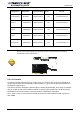
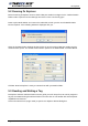
Antenna
Configuration
Outside
Dimension
Channel Setting
Max. Output
Power
FCC ID
L-W1 Antenna Ø 100mm Single Channel 1W
QHKLIBREADERLP101
Aero LI 230X262mm Single Channel 1W
QHKLIBREADERLP101
LSA 3 446X366mm Single Channel 1W
QHKLIBREADERLP101
LSA 4 230X262mm Single Channel 1W
QHKLIBREADERLP101
LSA 4 SHD 230X262mm Single Channel 1W
QHKLIBREADERLP101
2.2.4 In Canada
To reduce potential radio interference to other users, the antenna type and its gain should be so
chosen that the equivalent isotropically radiated power (e.i.r.p) is no more than that permitted for
successful communication.
This device has been designed to operate with the antennas listed below, and having a maximum
gain of -35 dBi. Antenna not included in this list or having a gain greater than -35 dBi are striclly
prohibited for use with this device. The require antenna impedance is 50 ohms.
LW-1, Aero LI, LSA-3, LSA-4 and LSA-4 SHD antennas meet this requirement with a gain less
than -35dBi.
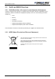
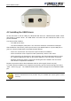
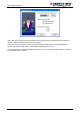
CAUTION: When using Medio P200L with LSA-4 SHD antenna, one must be sure a ferrite is
placed close to power supply jack connector (2 turns as shown below). The ferrite is
provided with LSA-4 SHD antenna.