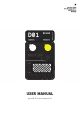
USER MANUAL plyon® flex development kit
This publication is protected by copyright. No part of the publication may be used, reproduced, or translated, in any form, without the prior written consent of tacterion GmbH. plyon and the plyon logo are trademarks of tacterion GmbH. tacterion and the tacterion logo are trademarks of tacterion GmbH. Other names and brands may be claimed as the property of others. © 2022 tacterion GmbH. All rights reserved. document version 1.
DISCLAIMER The technical data mentioned in the user manual and data sheet are compiled based on tacterion’s best knowledge; tacterion does not assume any warranty or liability for their accuracy, completeness, and merchantability. The plyon® flex development kit and its contents are engineering samples, meaning that the design of the product is not yet concluded and finally tested by tacterion. Engineering samples may be partially or fully functional and may differ from published product specifications.
The kit can only be purchased by business/enterprise customers and is not intended for personal consumer purchase. The kit may only be utilized by the original purchaser or acquirer, and may not be resold, distributed, leased, rented, or otherwise transferred, in whole or in part, or used in any finished product or production.
TABLE OF CONTENTS 1 1.1 1.2 1.3 1.4 1.5 1.6 2 3 4 5 6 6.1 6.2 6.2.1 6.2.2 6.2.3 6.3 6.3.1 6.3.2 6.3.3 6.4 6.5 6.6 7 7.1 7.2 7.3 8 9 9.1 9.1.1 9.1.2 9.1.3 9.1.
9.1.5 9.2 10 11 plyon flex® Slider D-01 PCB Recommendations For Integration Contact 41 42 43 44 SKIP TO QUICK START GUIDE document version 1.
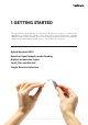
1 GETTING STARTED The plyon® flex development kit (dev kit) is designed to help you evaluate the capabilities of tacterion’s flexible touch and force sensor technology, utilizing capacitive and resistive readout. Due to its versatility, the plyon® flex sensor modules can be used to make many curved surfaces touch and force sensitive. Hybrid Readout (HFC) Excellent Signal Integrity under Bending Highly Customizable Layers Small, Thin and Durable Simple Electrical Interface document version 1.
1.1 WARNING LABELS To make risks clear, the following signal words and labels are used for safety notes. ATTENTION: Failure to follow the information provided within these warnings may result in damage to the sensor or electronics, injuries, or property damage. HINT: The user manual contains hints and tips, providing additional information about the technology, underlying principles, or other helpful pieces of information. document version 1.
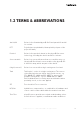
1.2 TERMS & ABBREVIATIONS dev kit/kit Refers to the Standard plyon® flex Development Kit and all its content. PET Polyethylene terephthalate, thermoplastic polymer of the polyester family. Product Refers to the products based on the plyon® flex sensor technology, including the dev kit and all its contents. Sensor module Refers to a sensor with more than one sensitive area, e.g.
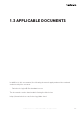
1.3 APPLICABLE DOCUMENTS In addition to this user manual, the following documents apply and must be read and understood by the customer: • Data sheet of plyon® flex standard sensors The documents can be downloaded following the links below. https://www.tacterion.com/technology/data-sheet document version 1.
1.4 INTENDED USE The content of the plyon® flex development kit is for the sole purpose of research and development, e.g. (i) evaluation of the general functionality of the materials, (ii) testing the properties and performance of the sensors, the readout electronics, and the software supplied and (iii) examining potential use in/with products.
1.5 INAPPROPRIATE USE The plyon® flex development kit and its content shall not be directly or indirectly assembled as a part or subassembly in any finished product. The plyon® flex development kit and its content are not intended for consumer or household use. The plyon® flex development kit and its content may not be sold, sublicensed, leased, rented, loaned, assigned, or otherwise distributed for commercial purposes by users, in whole or in part, or used in any finished product or production.
1.6 PERSONNEL QUALIFICATION Personnel working with the product must be sufficiently qualified to prevent serious injuries and property damage. • • • Only qualified personnel may work with the components of the plyon® flex development kit The personnel must have read and understood the user manual and other relevant documentation provided with the plyon® flex development kit National safety regulations and general safety instructions must be observed document version 1.
2 WARRANTY If the plyon® flex development kit is used as intended (see chapter 1.4), the warranty is valid for 12 months from the ex-works delivery date. document version 1.
3 PACKAGE CONTENTS 01x 02x 02x 01x 01x plyon flex® Stripe plyon flex® Medium plyon flex® Square plyon flex® Array with ZIF Connector plyon flex® Slider 01x 01x Core Unit D-01 PCB 01x 15x Micro-USB cable Jumper Wires document version 1.
4 QUICK START GUIDE Power the Board - 6.1 Connecting Sensors- 6.2 Interaction & feedback - 6.3 Switch between HFC & resistive - 6.4 Adjusting the reference resistor - 6.5 Proximity & feedback - 6.6 document version 1.
5 FIND YOUR WAY AROUND THE BOARD 1 3 4 9 10 11 2 1 2 3 4 5 6 7 8 9 10 11 5 6 7 8 Proximity Potentiometer and feedback LED Reference Resistor Potentiometer HFC/Resistive Switch USB Micro Slider feedback LEDs Single taxel feedback LEDs Reset Pin header connector Proximity channel Slider channel Standard - single taxel channels document version 1.
6 STANDALONE The „standalone“ mode of the plyon® flex development kit allows direct onboard interaction without having to connect additional hardware or installation of readout software. Its strength lies in intuitive and quick learning of how the sensors function and what affects sensor performance and characteristics most. For detailed signal analysis or even table top prototype mockup setups please visit the respective chapters „data stream“ or „prototype“. 6.
6.2 Connecting Sensors You can connect the plyon® flex sensors in two different ways: 1. directly connecting the crimped flex-tail of the sensor to the socket connector on the PCB. This way tangling cables are avoided and the setup can be kept clean and simple. 2. using jumper wires to bridge betwenn the PCB crimped flextail to have more flexibility in positioning the sensors. We added a set of jumper wires to the kit. Feel free to use any length of male/female jumper wires to fit your purpose.
6.2.1 Single Taxel Sensors plyon® flex Square (PFL-10020) plyon® flex Medium (PFL-10021) plyon® flex Stripe (PFL-10033) The following sketch shows the layout of the pins primarily used to connect individual single taxel sensors. Channel Common Channel Common Channel Common Channel Common Channel Common Channel Common 1 2 3 4 5 6 Please stick to the following schematic Incorrectly connected sensors may result in corrupted or no readout. document version 1.
6.2.2 Connecting the Array plyon® flex Array (PFL-10022) In order to connect the plyon® flex 4 taxel array sensor insert the flex-tail into the ZIF connector of the adapter board. It is crucial to connect it with the printed conductive traces facing down/the sensor module facing upwards as shown below. The ZIF adapter board is subsequently attached to the electronics as shown below. Make sure the silicone side of the sensor is facing you. document version 1.
6.2.3 Connecting the Slider plyon® flex Array (PFL-10023) The design of the sensor allows using the sensor 2 ways. SLIDER Channel 1 Common Channel 2 1. Regular: Silicone side up 2. Upside Down: PET side up (1) (2) document version 1.
6.3 LED Feedback The D-01 carries 3 areas (1-3) to provide realtime visual feedback of the interaction forces and one system status LED (4). proximity feedback LED (1) slider feedback LEDs (2) standard feedback LEDs (3) status LED (4) 1. proximity feedback LED: 2 color status diode indicating the approximation of e.g. a human hand once set up correctly. Only active with sensors connected to the „PROXIMITY“ socket. 2.
6.3.1 Standard Channel LED Array explained Clusters, Channels and feedback LEDs are labeled and numbered accordingly. Standard Channel 1 -> Standard LED 1, Standard Channel 2 -> Standard LED 2... We took a fairly simple approach of mapping increasing interaction forces to colors representing increased temperature. RGB „STANDARD“ LED color temperature scale: 4095 0 min. forces max. forces document version 1.
6.3.2 Special Case: the plyon® flex Array Due to the advanced routing of the sensor and the connector socket pin allocation the last 2 taxels of the Array sensor are reversed on the STANDARD LED array. plyon® flex Array taxel routing: 1 2 4 3 4 6 5 Exemplary readout for the plyon® flex Array: 3 document version 1.
6.3.3 plyon® flex Slider Feedback LEDs For the slider feedback unicolor white LEDs with a change in brightness are used. The logic behind it can be read as follows: 1. 6x1 LED array to indicate the finger position with 1 being closest to the flex-tail and 6 being the tip of the sensor. 2. The illuminated LEDs add up, e.g. for position 4, LEDs 1-4 remain active. 3.
6.4 Resistive and HFC readout HFC (hybrid force compensation): Our latest feature optimizes the sensor for static load by enabling an almost drift free readout over time. The most noticable change next to the drift minimization lies within the force required to actuate the sensor. Now that we are utilizing both, capacitive and resistive readout, the force required to actuate the sensor is noticably decreased. Activating HFC readout: 1. Set the switch to „ON“ position 2.
6.5 Adjusting the reference resistor The plyon® flex sensor changes resistance depending on the applied force. For the correct readout of the sensor, a voltage divider is used. The sensor is wired in series with a reference resistance and a voltage of 3.3V is applied. An analog-to-digital converter (ADC) is connected to the center node of the divider. By making use of the measured output voltage, the input voltage of 3.3V, and the reference resistance, the resistance of the sensor can be computed.
Adjusting the poti affects the resistive readout for: 1. standard single taxel channels 1-6 2. slider channel Some effects of increasing (clockwise) the reference resistor while in „resistive“ readout mode include: 1. how forces: the required onset force for the single taxel, array and slider is reduced 2. high forces: the sensors saturate quicker For the HFC readout being more complex, the felt difference adjusting the reference resistor are minor compared to the resistive only readout.
6.6 Proximity Detection The dedicated proximity channel utilizes the printed electronics conductors as an antenna. The proximity detection function needs to be adjusted for each sensor individually (amongst other things because the amount of printed conductive ink is different). That is what the right/upper rotary potentiometer is for. document version 1.
Here is how you tune in the proximity detection for each sensor layout: 1. Connect any of the following sensors: plyon® flex Square (PFL-10020) plyon® flex Medium (PFL-10021) plyon® flex Stripe (PFL-10033) plyon® flex Slider (PFL-10023) 2.
7 DATA STREAM RGB LEDs are nice and everything - but let‘s talk real sensor data here. For streaming the preprocessed data from the D-01 all it takes is a Windows or Mac OS based Computer that can host an external Micro USB device. In the following chapters we will lead you through setting up your system. 7.1 Connecting the D-01 to a Computer Use the enclosed USB cable (or any standard Micro USB cable) to connect the D-01 PCB to your computer. Two things should be happening: 1.
1. For logging your data stream, click on the “File” menu and select “Log…” to save the data in a text file on your PC.
7.3 Serial Graph Visualization - kst 1. Download Kst (link) application selecting the version for your operating system (for Windows please download the 32bit version), this will lead you to a new webpage: click on the green “Code” button and then “Download ZIP”. 2. Unzip the archive 3. Download the tacterion specific kst configuration file (link) and extract the file from the ZIP archive 4. (Connect the electronics to the PC via USB) 5. Open Tera Term by launching the “ttermpro.exe” 6.
8 PROTOTYPE The following sketch shows the pin header connector on the D-01. The pin header connector can be used to supply power as well as connecting the readout electronics to a 3rd party microcontroller board like an arduino. 5 3 1 6 4 2 # Name Voltage Type 1 Rx 5V tolerant Input UART communication line, data input 2 VDD 3.3V Power If USB is connected: 3.3V out (Imax = 50mA) If no USB is connected: 3.
ATTENTION: Connect the readout electronics to one power supply only, either USB or through the pin header input. Connecting the readout electronics to two power supplies may result in damages to the devices and sensors, injury, or property damage. HINT: VDD 3.
9 ADDITIONAL INFORMATION 9.1 SENSORS 9.1.1 plyon flex® Square Model No.: PFL-10020 Type: single taxel Sensing area: 16x16 mm Module size: 24x24x0.5 mm TrueZero HFC Proximity + + + Description: The „Square“ is a well rounded small sized single taxel sensor. Its sensing area is predestined to prototype single button interfaces with multiple force levels. It is the closest of our reference designs to a generic mechanical button. document version 1.
9.1.2 plyon flex® Medium Model No.: PFL-10021 Type: Single Taxel Sensing area: 10x50 mm Module size: 18x58x0.5 mm TrueZero HFC Proximity + + + Description: The „Medium“ is an off the shelf medium sized single taxel sensor. The increased sensing area allows to cover more surface area and allows for the first operator presence sensing prototype builds.
9.1.3 plyon flex® Stripe Model No.: PFL-10033 Type: Single Taxel Sensing area: 8.5x90 mm Module size: 16x100x0.5 mm TrueZero HFC Proximity + + + Description: The „Stripe“ is our longest single taxel sensor and made for operator presence detection e.g. in handheld devices. Its dimensions are optimized to fit a broad range of hand sizes. document version 1.
9.1.4 plyon flex® Array Model No.: Type: Sensing area: Module size: PFL-10022 Taxel Line Array Taxelsize: 10x10 mm, Gap between Taxels: 4mm 18x58x0.5 mm TrueZero HFC Proximity + + - Description: The „Array“ is a medium sized multi taxel line array. Multiple sensing elements in a close proximity to each other allow not only for single taxel (single button) readout but also for inter taxel transition & directional gestures. It would be possible e.g.
9.1.5 plyon flex® Slider Model No.: PFL-10023 Type: Resistive Slider Sensing area: 10x50mm Module size: 18x58x0.5 mm TrueZero HFC Proximity + + Description: The „Slider“ is an advanced layout that optimizes accuracy and sensitivity for sliding gestures (one direction). It detects position and force applied. Multitouch gestures are not possible. The slider provides a value range from 0-4095. The sensing area can logically be segmented to achieve different funcitonal areas.
9.2 D-01 PCB feedback LED potentiometers feedback LED switch feedback LED reset button pin header connector USB Micro HCU sensor connector pins Model No.: EBS-10018 Module size: 117x70x20 mm Power Supply: 5V Communication Interfaces: USB (CDC/Virtual COM Port), UART, 6 PIN document version 1.
10 RECOMMENDATIONS FOR INTEGRATION The sensor can be integrated into your prototype product for evaluation and testing in different ways. Common integration options are: (a) (b) fastening by friction double-sided adhesive tape (a) is a non-destructive option and can be realized e.g. by positioning the sensor as a layer between the product surface and a protective layer. HINT: The area above the four single tactile sensors can be used to secure the sensor in place, e.g. with a latch.
11 CONTACT Thank you for purchasing our product and trusting our company. We are always available to answer your questions on this product and other solutions. Ask and challenge our sales representative, or get in contact via the options mentioned below: tacterion GmbH Nymphenburger Straße 5 80335 Munich – Germany Tel.: +49 (0) 89 452 47 750 support@tacterion.com www.tacterion.com document version 1.